Portable battery charger powered by internal combustion engine

Active Publication Date: 2008-12-30
WHEATLEY VANESSA MARIE +1
View PDF18 Cites 29 Cited by
  • Summary
  • Abstract
  • Description
  • Claims
  • Application Information

AI Technical Summary

Benefits of technology

[0008]The present invention provides a portable battery charger that is powered by a small to moderate sized gasoline, diesel, or propane internal combustion engine. The portable device incorporates a recoil or an electric starter and an engine throttle that can be used to vary the voltage/current output of the charger. The charger uses a generator that includes a permanent magnet alternator equipped with a belt tension adjustor arm, a heavy duty diode rectifier, and a circuit protector. The primary components of the charger (the engine and the generator) are positioned on a wheeled, heavy-gauge steel, roll-around cart that makes the charging system easily portable. The two-wheeled cart includes a gooseneck handle, allowing the user to steer the charger from one point to another. Positioned on this handle is a control box with an anti-spark keyed switch that blocks any discharge or spark from traveling through the charging wires until the switch is turned on. This switch control facilitates the safe hook-up of the charging clamps while the charger (engine) is running. The charging system also includes heavy duty cables between the generator and the anti-spark control box, as well as well as out from the control box to insulated clamps that

Problems solved by technology

For environments where lead-acid batteries are utilized apart from automotive vehicles the ability to recharge the batteries

Method used


Image

  • Portable battery charger powered by internal combustion engine
  • Portable battery charger powered by internal combustion engine
  • Portable battery charger powered by internal combustion engine

Examples


Embodiment Construction

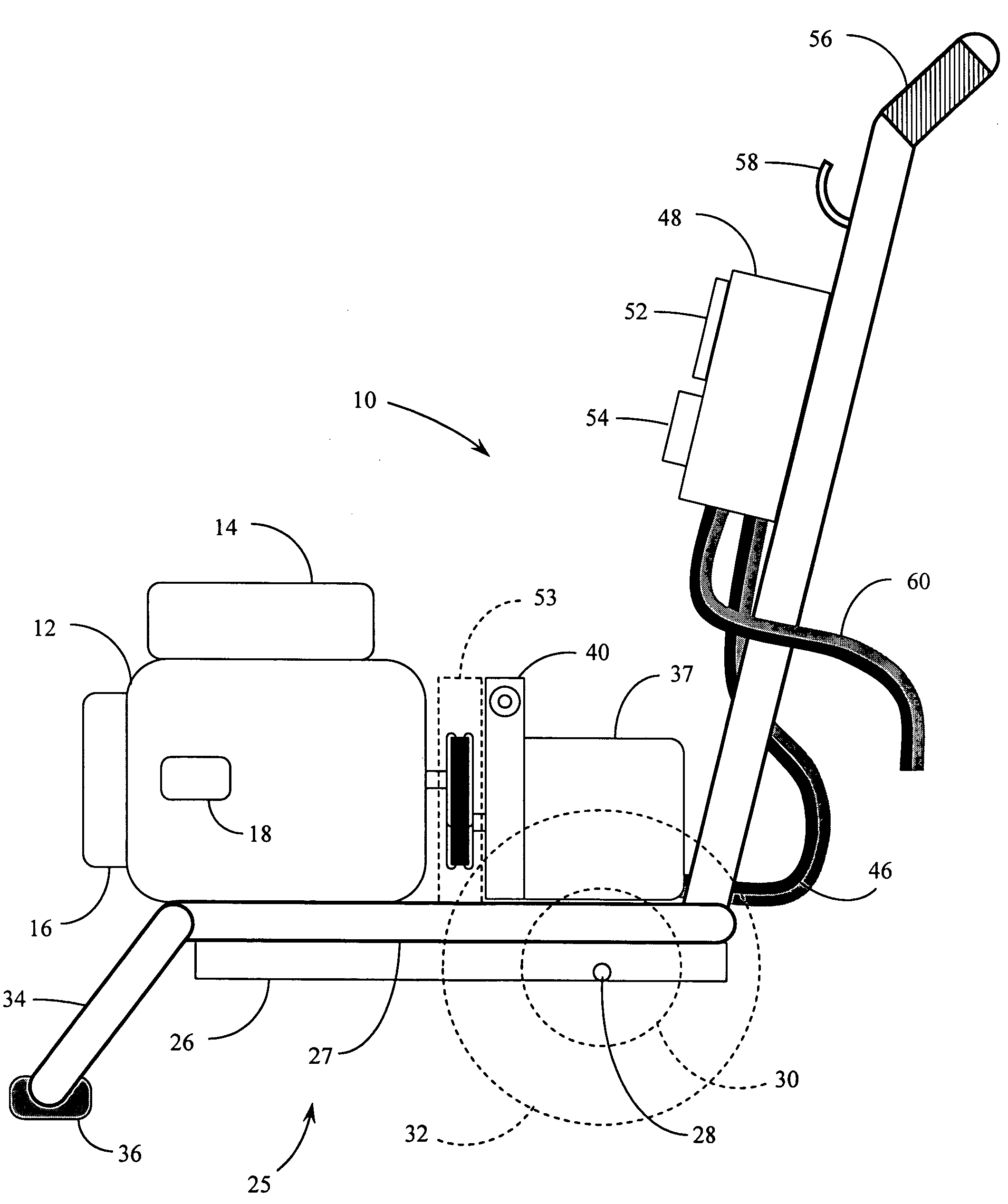
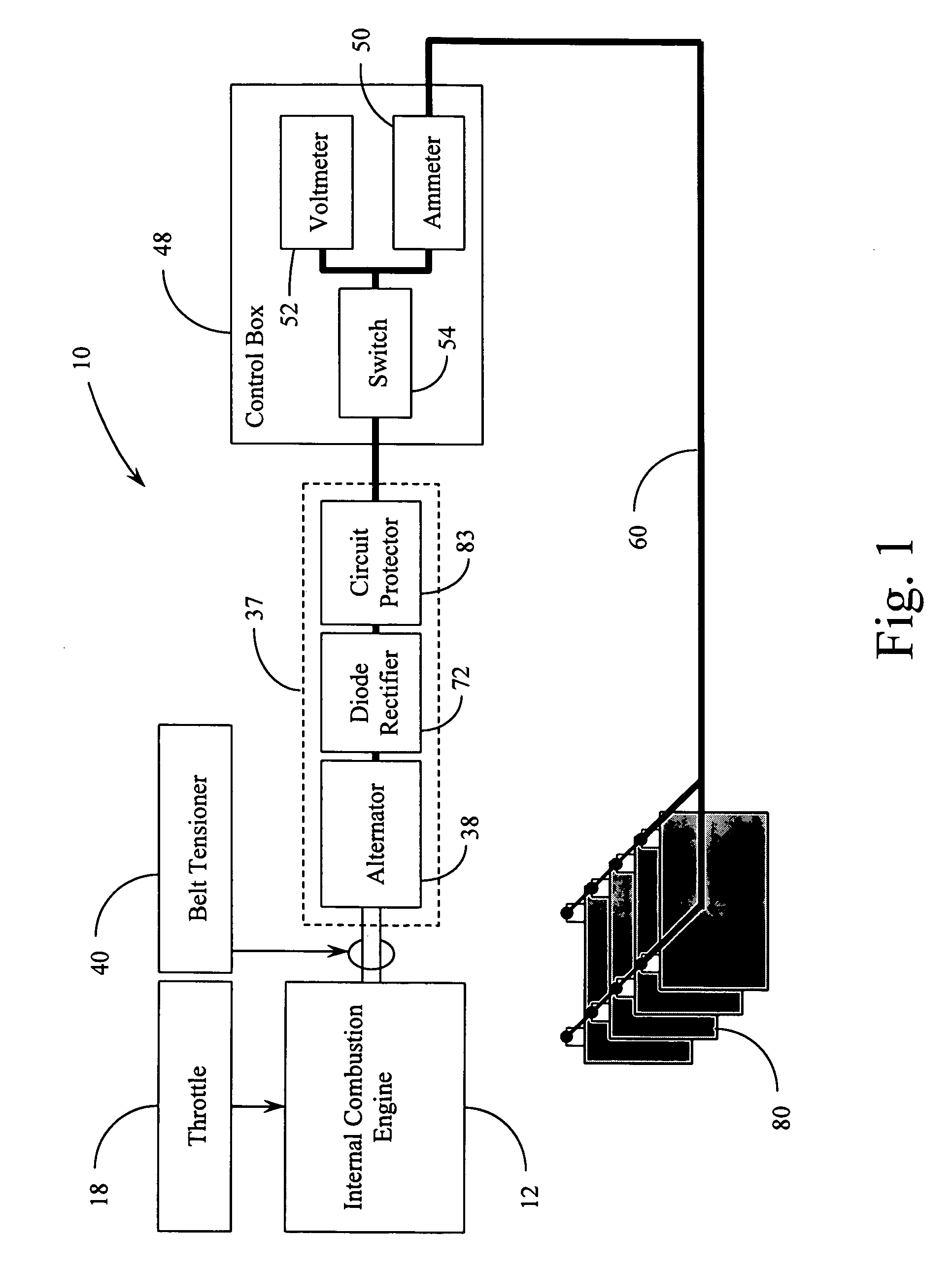
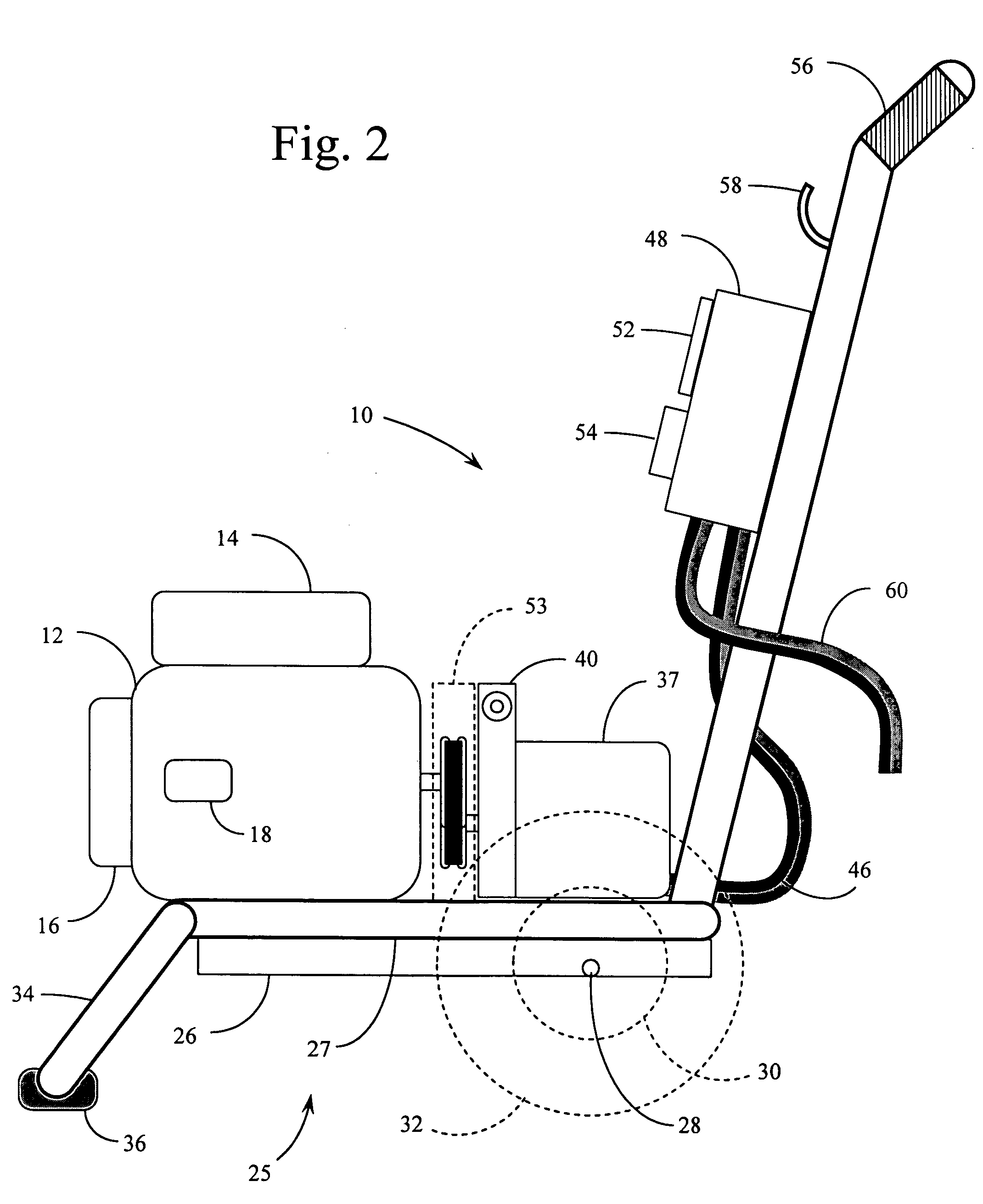
[0014]Reference is first made to FIG. 1, which provides a simple block diagram of the overall structure and function of the battery charging system of the present invention. As shown in FIG. 1, the battery charging process begins with the operation of internal combustion engine 12, being regulated by engine throttle 18 which can be adjusted manually to control the number of RPM's (and therefore the power) that the engine puts out. The power output of the engine 12 is used to turn alternator 38 within the generator system 37, the rotation being transferred to the alternator 38 through the engine's output driveshaft through a V-belt and pulley arrangement described in more detail below. The engine drive pulley is connected to a pulley on the input driveshaft of the alternator 38 with a standard V-belt through a belt tensioner 40, which is used to tighten or loosen the V-belt. The belt tensioner 40 supplements the function of the engine throttle 18 wherein the tightness of the V-belt h...


PUM


Abstract

A portable battery charger that is powered by a gasoline, diesel, or propane engine. The portable device incorporates a recoil or electric starter and an engine throttle lever that can be used to vary the RPM of the engine and therefore the voltage/current output of the charger. The charger uses a permanent magnet alternator equipped with a belt tension adjustor arm and a heavy duty diode rectifier. The components of the charger (the engine and the alternator) are positioned on a wheeled, heavy-gauge steel, roll around cart that makes the charger easily portable. The two-wheeled cart includes an extended handle, allowing the user to move and steer the charger into position for use. Positioned on this handle is a control box with an anti-spark keyed switch that blocks any charging current from traveling through the charging cables until the switch is thrown. This control facilitates the safe hook-up of the charging clamps while the charger (engine) is running. The charger includes heavy duty cables between the alternator and the anti-spark control box, and additionally out from the control box to insulated clamps that are used to connect to the batteries. The control box additionally includes an ammeter and a voltmeter to indicate the charging current and voltage. The portable charger structured in this manner can be used to charge a non-specific number of batteries in parallel, typically in less than 2-4 hours depending on the size and state of the existing battery charge. The charger may also be used in the process of equalizing a bank of batteries to facilitate a reduction in stratification and sulfation.

Description

BACKGROUND OF THE INVENTION[0001]1. Field of the Invention[0002]The present invention relates generally to portable devices for charging electrical storage cells (batteries). The present invention relates more specifically to a portable, wet cell battery charger, powered by an internal combustion engine, the charger utilizing a high-efficiency permanent magnet alternator / generator connected through a cut-off switch to battery clamps or clips that may be attached to the terminals of a bank of batteries.[0003]2. Description of the Related Art[0004]Batteries or electric storage cell devices are commonly used to provide electrical power to a variety of devices in environments where alternating current electric power sources are not available. Batteries generally take one of two forms that may be classified as either wet cell batteries or dry cell batteries. Some of the most common types of wet cell batteries used in a rechargeable manner are lead-acid batteries that position a number of...

Claims


Application Information

Patent Timeline
IPC IPC(8): H02J7/00H02J9/00
CPCH02J7/1415
Inventor RUIZ, RAFAEL J.
Owner WHEATLEY VANESSA MARIE
Why Eureka
Try Eureka