Filament lamp

a technology of filament lamps and filaments, applied in the field of filament lamps, can solve the problems of difficult to impart the desired physical property after light heat treatment, narrow defined regions cannot be controlled in such a manner, and achieve the effect of high precision

Inactive Publication Date: 2008-12-30
USHIO DENKI KK
View PDF18 Cites 11 Cited by
  • Summary
  • Abstract
  • Description
  • Claims
  • Application Information

AI Technical Summary

Benefits of technology

[0035]As is described below, the inventors have invented a filament lamp with a completely different arrangement than a conventional arrangement and a heat treatment device of the light irradiation type using this filament lamp. This heat treatment device of the light irradiation type makes it possible to overcome the above described disadvantages of the conventional heat treatment device of the light irradiation type.
[0049]Since compared to the conventional example in which U-shaped lamps are used, in the heat treatment device of the light irradiation type in accordance with the invention, filament lamps are used in which the distance between the respective filaments to be arranged in the bulb can be reduced to an extreme degree, the effect of the distance between the filaments which is a not an emitting space can be reduced to a minimum, by which it becomes possible to make unwanted scattering of the distribution of the illuminance on the article to be treated extremely small. Since, in the vertical direction of the heating device, there is no vertical part of the lamp, the space corresponding to this within the lamp unit is no longer required, by which the heating device can be made smaller.

Problems solved by technology

Therefore, control cannot be exercised in such a manner that the above described certain region and the other region are shifted into suitable temperature state.
This means that the irradiance in the above described, narrow defined region cannot be controlled such that the two temperatures become uniform.
At the treatment temperature of the article to be treated, therefore, an unwanted temperature distribution occurs, resulting in the disadvantage that it becomes difficult after light heat treatment to impart the desired physical property to the article to be treated.
However, if the defined region is not centrosymmetric to the middle of the semiconductor wafer, the above described disadvantage cannot be advantageously eliminated because the semiconductor wafer which is the article to be treated is rotated.
Furthermore, in such a heat treatment device, it is possible for the following disadvantages to occur in practice.
However, since only the horizontal region in which the filament is located contributes to emission, the individual lamps are apart from one another over a space which cannot be ignored.
Therefore, it can be imagined that it is relatively difficult to reduce the temperature distribution which arises in the vicinity of the region which is located directly underneath the above described space, even if an attempt is made to carry out heating according to the temperature change of the respective zone.
Furthermore, such a heat treatment device is undesirable with respect to making the space smaller, since recently there has been a trend toward an extreme reduction in the size of the space (mainly vertically) for arrangement of the lamp units, and since therefore when a U-shaped lamp is used, a space corresponding to the vertical regions of the lamp is required.
If an attempt is made to increase the number of filaments, therefore the number of metal foils inevitably increases.
For this reason, there were cases in which difficulties occurred in manufacture or poor sealing such as leaks and the like occurred more often.
When poor sealing, such as a leak or the like occurs, air is mixed into the bulb of the filament lamp, resulting in the disadvantage of burning through by oxidation of the filaments.
Finally, the disadvantage of damage to the bulb occurs, by which the filament lamp becomes unusable.

Method used


Image

  • Filament lamp
  • Filament lamp
  • Filament lamp

Examples


Embodiment Construction

(A. Arrangement of a Filament Lamp)

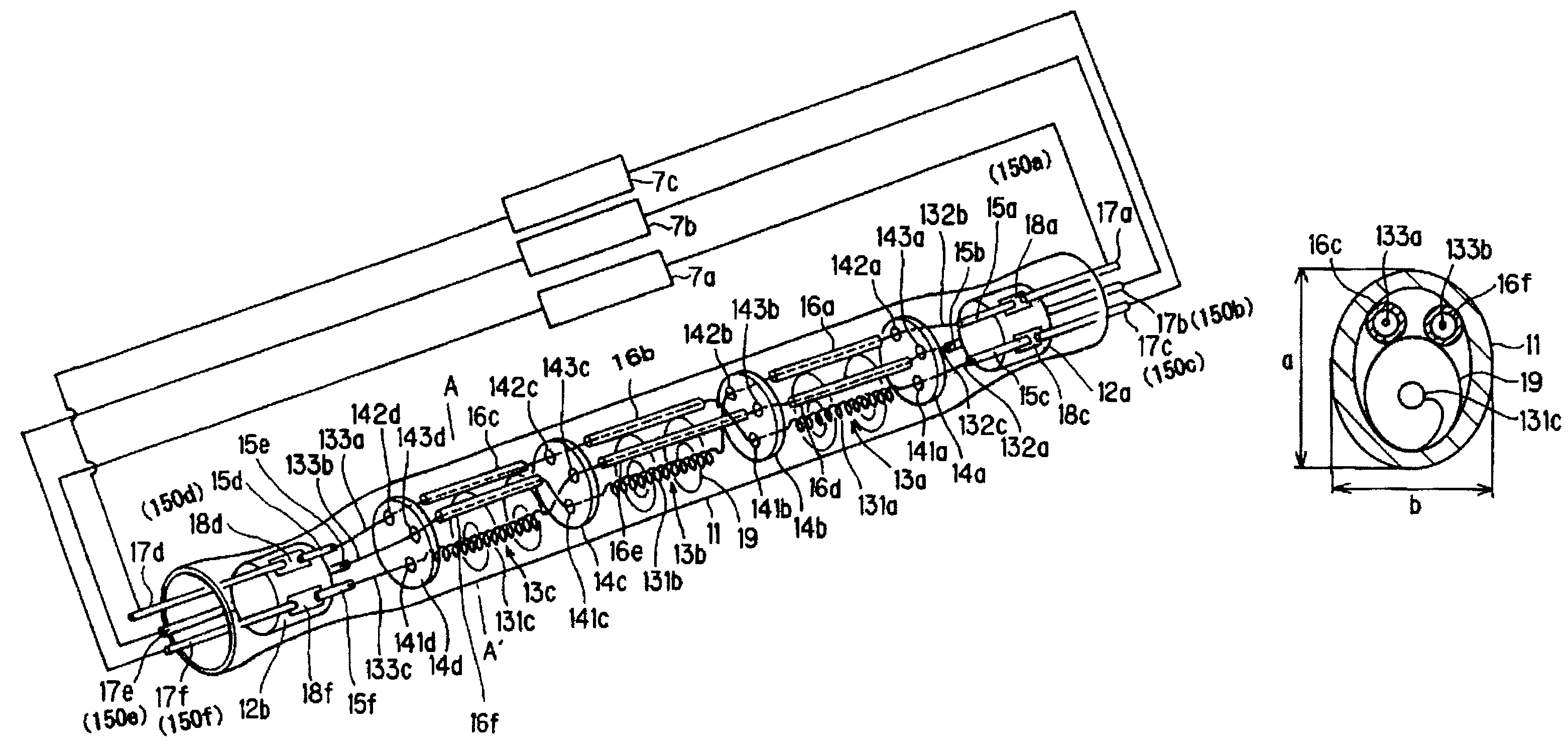
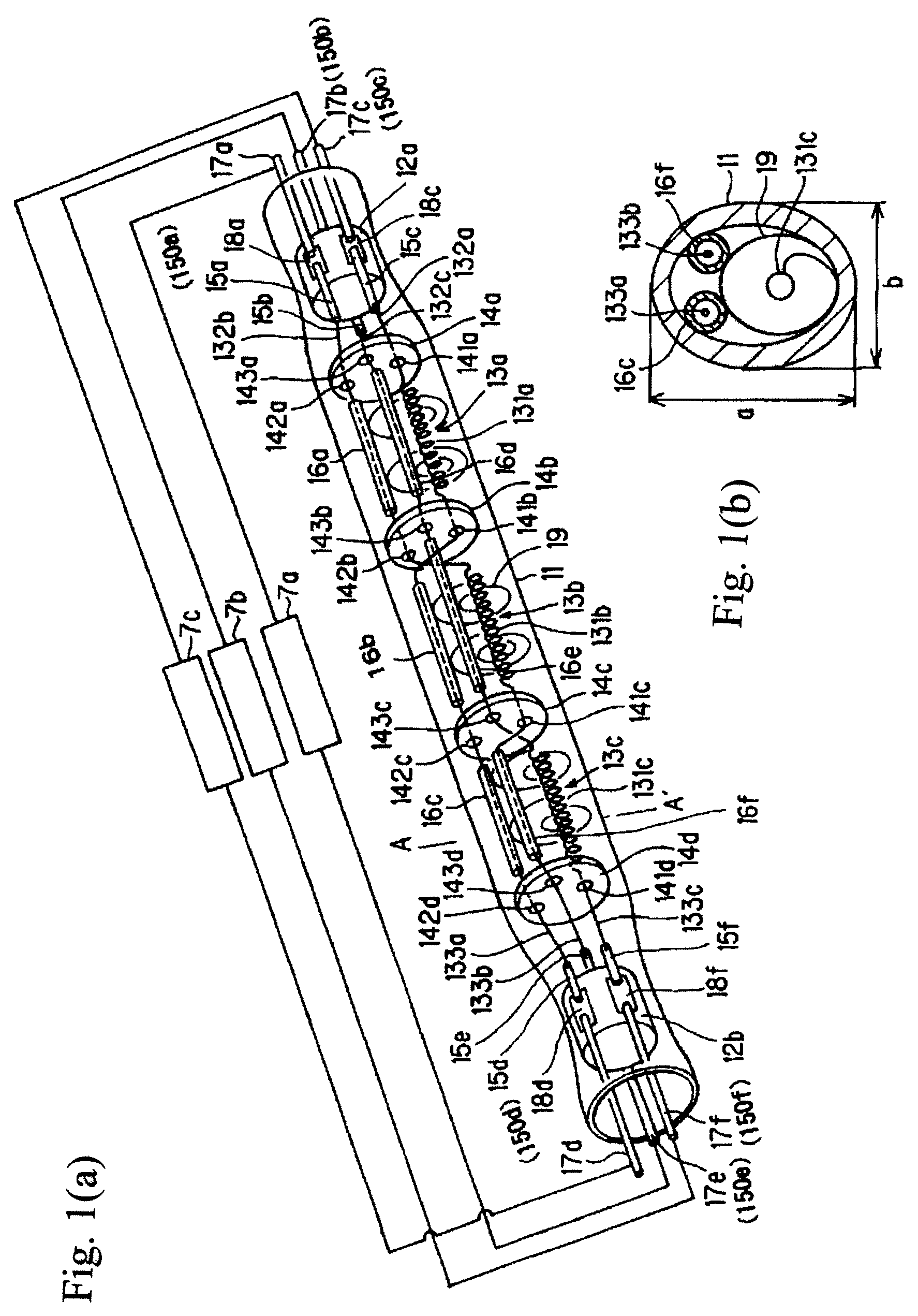
[0061]FIGS. 1(a) &1(b) show an embodiment of a filament lamp in accordance with the invention which is comprised of bulb 11 made of a transparent material such as, for example, silica glass or the like. As can be seen from transverse cross-sectional view of FIG. 1(b), the bulb has an oblong cross-sectional shape, but a circular shape can also be used. The term “oblong” is to be understood as encompassing all shapes in which the length a in the lengthwise direction is greater than the length b in the direction perpendicular to the lengthwise direction the cross-sectional shape, as is shown in FIG. 1(b). By using an oblong shape, the above described filament bodies and insulating tubes can be easily arranged in the direction shown in FIG. 1. The bulb 11 is filled with a halogen gas, and furthermore, there are three filament bodies 13a, 13b, and 13c in it. On the inside in the vicinity of the two ends, there are rod-shaped insulators 12a, 12b for seal...


PUM


Abstract

A filament lamp in which the article to be treated can be uniformly heated, and in which the disadvantage of poor sealing or the like does not arise even in the case of inserting a host of metal foils into a hermetically sealed portion is achieved in a filament lamp in the bulb of which there are several filament bodies, in which filaments and leads for supply of power to the filaments are connected to one another, and in which, on an end of the bulb, there is a hermetically sealed portion in which there is a rod-shaped sealing insulator on the periphery of which several electrically conductive components that are connected to the filaments are arranged spaced from one another.

Description

BACKGROUND OF THE INVENTION[0001]1. Field of the Invention[0002]The invention relates to a filament lamp. The invention relates especially to a filament lamp for irradiation of an article to be treated with light which is emitted for purposes of heating of the article to be treated.[0003]2. Description of Related Art[0004]In semiconductor manufacturing, generally, heat treatment is used in different processes, such as a layer formation, oxidation-diffusion, diffusion of impurities, nitriding, layer stabilization, silicide formation, crystallization, ion implantation activation and the like.[0005]To increase the yield and quality in semiconductor manufacture, rapid thermal processing RTP is desirable, in which the temperature of the article to be treated, such as a semiconductor wafer or the like, is rapidly raised or lowered. In RTP a heat treatment device of the light irradiation type (hereinafter also called only a heating device) using light irradiation from a light source, such ...

Claims


Application Information

Patent Timeline
Patent Type & Authority Patents(United States)
IPC IPC(8): F24C7/00
CPCH01J5/32H01K1/38H01K5/02
Inventor MIZUKAWA, YOICHIINAOKA, NORIHIROKITAGAWA, TETSUYA
Owner USHIO DENKI KK
Why Eureka
Try Eureka