
Projectile sealing arrangement

a technology of sealing arrangement and projectile, which is applied in the direction of firing/trigger mechanism, ammunition loading, rockets for air display, etc., can solve the problems of reducing the relative complexity and cost of manufacturing barrel assemblies utilizing operative sealing engagement with the barrel, and achieves the effect of reducing the relative complexity and cost of manufacturing barrel assemblies

Inactive Publication Date: 2009-01-13
DEFENDTEX
View PDF46 Cites 11 Cited by
  • Summary
  • Abstract
  • Description
  • Claims
  • Application Information

AI Technical Summary

Benefits of technology

"The invention is a sealing arrangement for a barrel assembly of a weapon where multiple projectile assemblies are axially disposed in abutting relationship within a barrel. Each projectile assembly is associated with a discrete propellant charge and includes a rearward opening and a forward portion for sealing engagement with the rearward opening of another projectile assembly. The sealing arrangement ensures that the discrete propellant charges for trailing projectiles are sealed within their respective cavities during application of a compressive load to abutting projectile assemblies. The invention also includes a chain of projectiles where each projectile assembly comprises a head portion and a tail portion and a releasable coupling is disposed between the tail portion of a leading projectile and a head portion of a trailing projectile."

Problems solved by technology

However the relative complexity and cost of manufacturing barrel assemblies utilising operative sealing engagement with the barrel detracts from some applications of the applicant's barrel assemblies, especially where high volume, low cost manufacture is anticipated.

Method used


Image

  • Projectile sealing arrangement
  • Projectile sealing arrangement
  • Projectile sealing arrangement

Examples


first embodiment

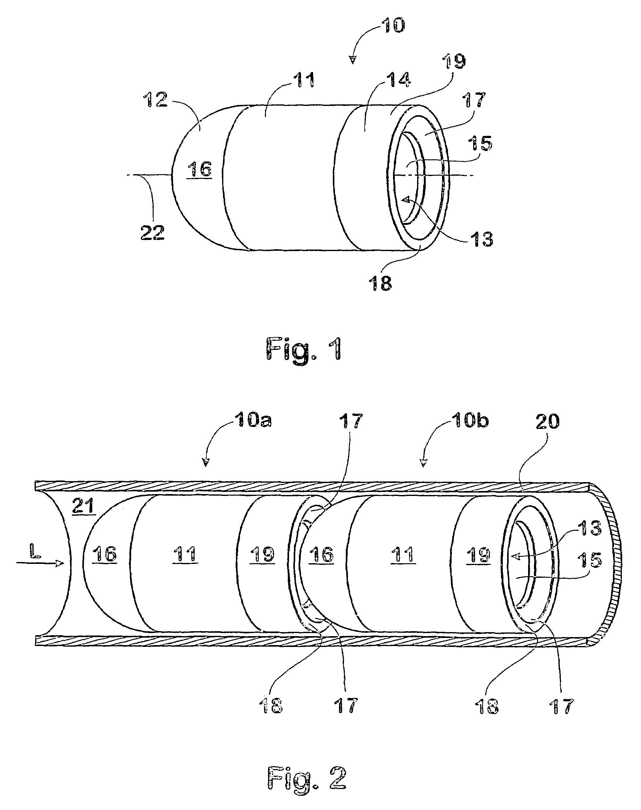
[0044]The projectile assemblies 10 of the first embodiment illustrated in FIGS. 1 and 2 each include a body 11 having a head or forward portion 12 and a mouth or rearward opening 13 at a tail portion 19, which opening communicates with a cavity 14 provided in the projectile body. The cavity 14 contains a discrete propellant charge 15 together with ignition means (not shown) for igniting the propellant charge. It will be appreciated that upon ignition of the propellant, suitably by electronic control means, combustion products including propellant gas will exit the projectile cavity 14 via the mouth 13 at the tail 19 of the projectile with considerable force.

[0045]In the first embodiment, a forward sealing surface 16 of the projectile head 12 is convex, having a simple hemispherical shape, whilst the mouth 13 has a peripheral sealing surface 17 that is provided or formed, at least in part, with a complementary concave shape to the hemispherical sealing surface 16 of head 12. The prec...

second embodiment

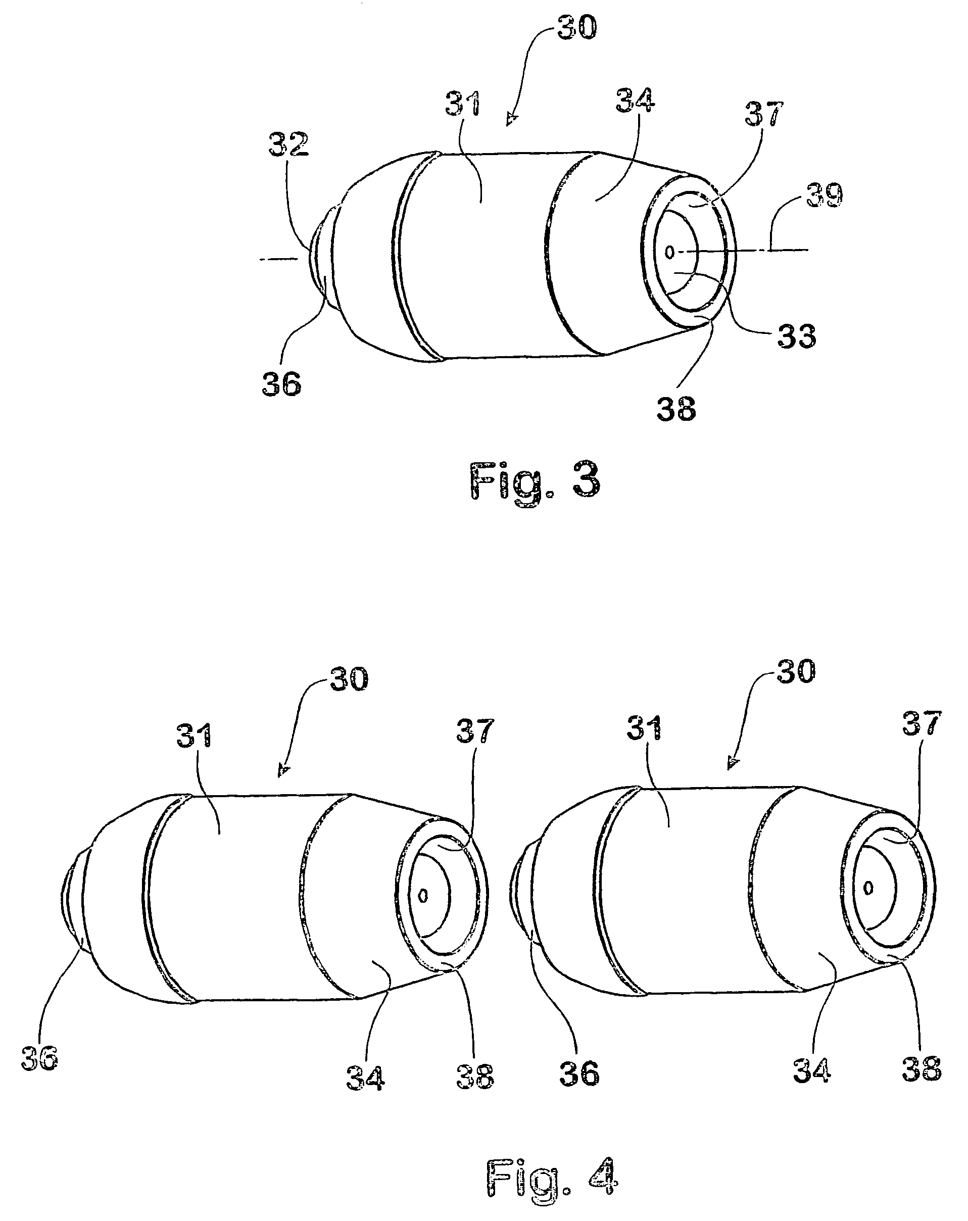
[0050]A projectile 30 in accordance with the invention is illustrated in FIG. 3. The projectile 30 includes a body 31 having a reduced diameter head or forward portion 32 and a mouth or rearward opening 33 at a tail portion which mouth communicates with a cavity (not shown) provided in the projectile body. The projectile body 31 includes a frustro-concial tail portion 34 which terminates at an annular rear face 38 having a reduced diameter relative to the projectile body generally. The internal cavity contains a discrete propellant charge 35 together with ignition means (not shown) for igniting the propellant charge. The arrangements for igniting the propellant charge may suitably be similar to those described in the earlier International Patent Application PCT / AU94 / 00124, assigned to the present applicant.

[0051]A forward sealing surface 36 is provided on the projectile head, together with a complementary rearward sealing surface 37 at the periphery of the rearward opening 33, which...

third embodiment

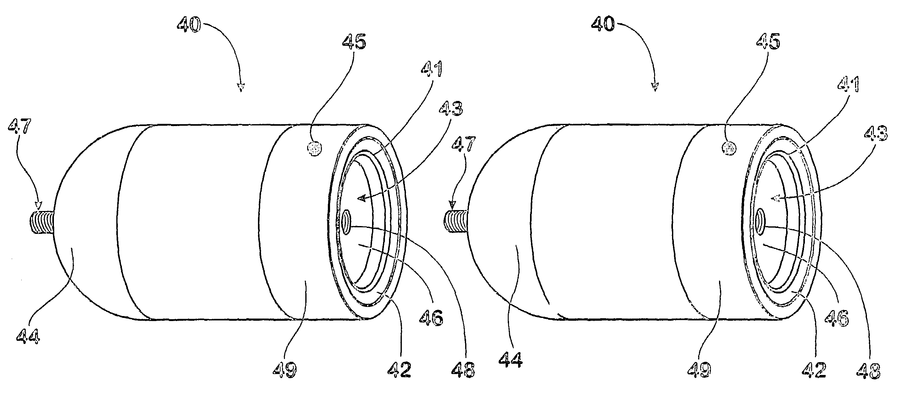
[0054]In other variations of the third embodiment, the sealing means may comprise an adhesive sealing material that forms a seal between abutting projectile assemblies in situ, and might also function to retain a plurality of projectiles in a chain for ease of loading into a barrel. A propellant charge 45 is retained with the body of the projectile assembly 40, and may be formed as a solid block or as flowable material, such as powder or granules, as in the present embodiment.

[0055]This embodiment further includes a closure for the rearward opening 43, in the form of a burstable disc 46, for retaining the flowable propellant charge 45. The closure, which may alternatively be formed of a combustible material rather than a burstable disc, includes retaining means that releasably engage with complementary retaining means on an adjacent projectile head. The retaining means in the present embodiment are formed by a spigot member 47 on the head, and by a socket member 48 provided in the b...


PUM


Abstract

A projectile sealing arrangement for a barrel assembly of a weapon wherein a plurality of projectile assemblies (10) are axially disposed in abutting relationship within a barrel (20), each projectile assembly (10) including a body (11) associated with a discrete propellant charge (15); said sealing arrangement comprising rearward opening (13) communicating with cavity (14) provided in said projectile assembly (10) for retaining the discrete propellant charge (15) and a forward portion (16) of an abutting projectile arranged for operative sealing engagement with a complementary portion (17) of the rearward opening (13). The sealing arrangement suitably includes surface portions of complementary shapes such that, during application of a compressive load (L) to abutting projectile assemblies (10), discrete propellant charge (15) is scaled within the cavity (14). There is also disclosed and claimed a chain of individual projectiles connected head to tail by complementary spigot and socket members.

Description

BACKGROUND OF THE INVENTION[0001]1. Field of the Invention[0002]This invention relates to projectile sealing arrangements for barrel assemblies wherein a plurality of projectile assemblies are disposed axially in abutting relationship within a barrel and associated with discrete propellant charges for selectively propelling respective projectiles sequentially from the barrel.[0003]The invention relates particularly, although not exclusively, to barrel assemblies for weapons that employ electrical or electronic activation of ignition means for igniting the discrete propellant charges.[0004]2. Discussion of the Background Art[0005]The projectile sealing arrangements for barrel assemblies described in earlier International Patent Applications assigned to the present applicant, including PCT / AU94 / 00124, utilise operative sealing engagement between each projectile assembly and the bore of a barrel containing the projectile assemblies.[0006]An important function of operative sealing engag...

Claims


Application Information

Patent Timeline
Patent Type & Authority Patents(United States)
IPC IPC(8): F42B5/03F41A9/72F42B5/16F42B14/00
CPCF42B5/035F42B5/16F42B30/00F42B14/00
Inventor BAMBACH, RAMON JOHN
Owner DEFENDTEX
Learn More