Centrifugal fan

a centrifugal fan and fan body technology, applied in the direction of machines/engines, stators, liquid fuel engines, etc., can solve the problems of increasing the load on the motor, deteriorating the blowing performance of the centrifugal fan, increasing noise, etc., to prevent the deterioration of blowing performance and noise generation

Active Publication Date: 2009-01-13
NIDEC SERVO CORP
View PDF14 Cites 16 Cited by
  • Summary
  • Abstract
  • Description
  • Claims
  • Application Information

AI Technical Summary

Benefits of technology

[0015]The purpose of the present invention is to solve the above-mentioned problems by providing an improved centrifugal fan, which is capable of preventing deterioration of the blowing performance and generation of the noise that are caused by the backflow and the recycling flow during low air quantity operation without increasing the size in the axial direction, the size of the impeller and the inertial mass.
[0022]With this construction, since the insertion of the annular rib into the recess portion forms a wall in an airflow path directed to the air inlet, the airflow directed to the air inlet returns back to the space between the blades, which can prevent generation of backflow and recycling flow. This prevents deterioration of the blowing performance and generation of the noise during low air quantity operation.
[0023]Since the structure of the present invention returns airflow back to the space between the blades without using the seal effect used in the prior art, it does not require high manufacturing accuracy, which can reduce the manufacturing cost. Further, since the annular rib is formed on the housing, it does not increase the axial size of the impeller and the inertial mass thereof. Therefore, the annular rib has little effect on the axial size of the centrifugal fan and the load on the motor.

Problems solved by technology

Such backflow B and recycling flow C deteriorate the blowing performance of the centrifugal fan 1 and increase the noise.
Further, since the jutted portion is formed on the impeller, the inertial mass of the impeller becomes larger, which increases load on the motor.
Further, the publication of Japanese unexamined patent application No.
However, since the fan of the publication is constructed to reduce the backflow by seal effect, a high manufacturing accuracy is required to satisfy the seal effect, which increases a manufacturing cost.
Further, since the shield plate is formed on the impeller, both the axial size of the impeller and the inertial mass of the impeller become larger, which increases the axial size of the centrifugal fan and load on the motor.

Method used


Image

  • Centrifugal fan
  • Centrifugal fan
  • Centrifugal fan

Examples


Embodiment Construction

[0036]Hereinafter, an embodiment of a centrifugal fan according to the present invention will be described with reference to the drawings.

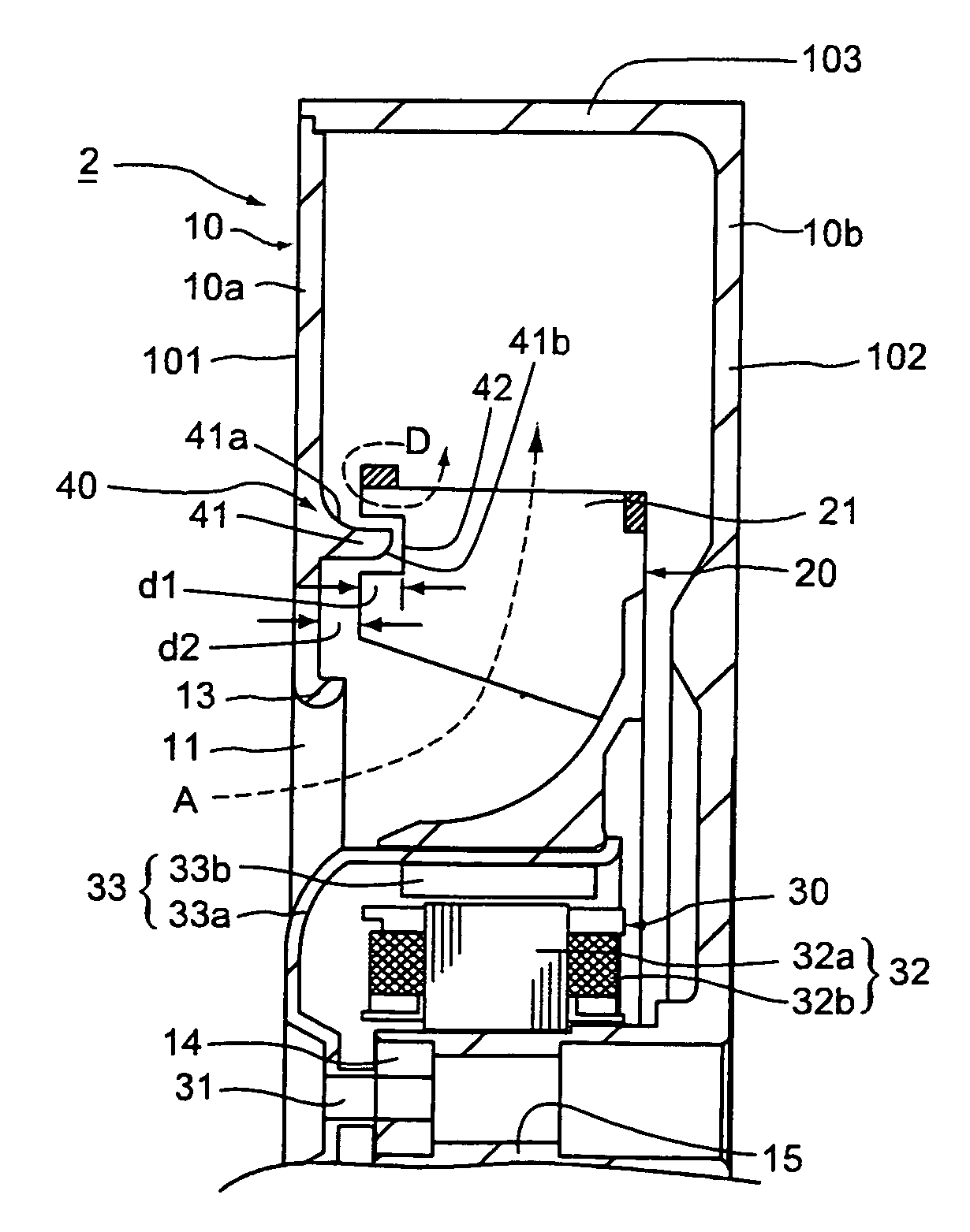
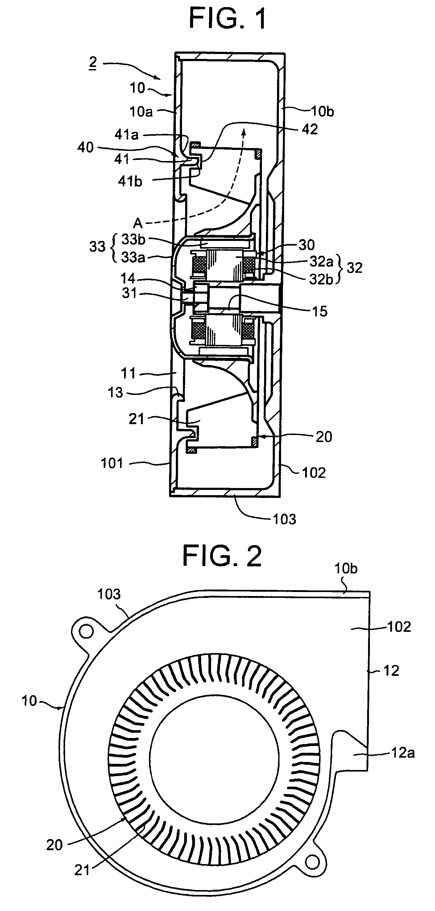
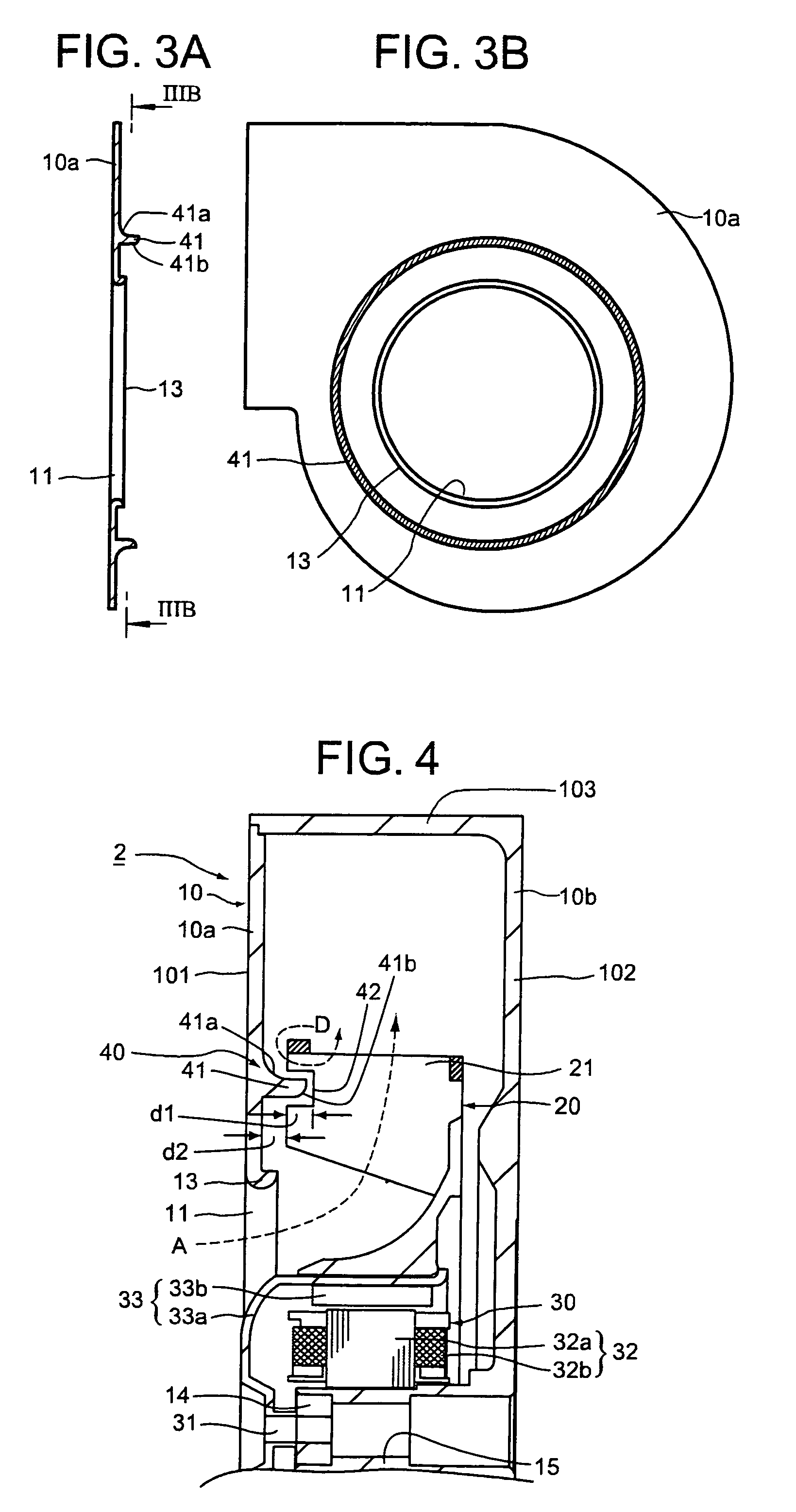
[0037]FIG. 1 is a sectional view of the centrifugal fan 2 of the embodiment in a plane parallel to a rotating shaft, FIG. 2 is a front view of the centrifugal fan 2 shown in FIG. 1 when a first casing is removed, FIG. 3A is a sectional view of the first casing of the centrifugal fan 2 shown in FIG. 1, FIG. 3B is a sectional view of the first casing shown in FIG. 3A along a IIIB-IIIB line viewed from inside, and FIG. 4 is an enlarged sectional view of the upper half of the centrifugal fan 2 shown in FIG. 1. Since the outward appearance and the generic construction at the inside of the centrifugal fan 2 of the embodiment are identical to that of the prior art, the same parts are described with the same reference numbers.

[0038]The centrifugal fan 2 of the embodiment is provided with a scroll casing 10 that has first and second flat base walls 101 and...


PUM


Abstract

A centrifugal fan includes a scroll casing having first and second flat base walls, and a circumferential side wall. An air inlet is formed on a center portion of the first base wall and an exhaust port is formed on the circumferential side wall. An airflow correction mechanism that forms smooth airflow when an impeller rotates is provided. The mechanism has an annular rib that is formed on the inside surface of the first base wall so as to be jutted to the side of the second base wall and to be concentric with the rotating shaft, and a recess portion that is formed on every blade of the impeller so that the annular rib is inserted therein with a predetermined gap. The annular rib and the recess portion are configured to change the direction of airflow directed to the air inlet back to a space between the blades.

Description

BACKGROUND OF THE INVENTION[0001]The present invention relates to a centrifugal fan that collects airflow taken in from an air inlet formed at the center of one flat base wall of a scroll casing and discharges the airflow from an exhaust port formed on a circumferential side wall in a centrifugal direction. More particularly, the present invention relates to a mechanism to prevent backflow during fan operating.[0002]Centrifugal fans, which use DC brushless motors especially, are widely used to cool electronic components of OA (office automatic) equipment such as a personal computer, a copying machine, a liquid crystal projector and a disk array because they can not only make the motors compact and light in weight but also control air quantity easily due to easy control of the motor.[0003]A prior art of such a centrifugal fan will be described with reference to FIG. 6 through FIG. 8. FIG. 6 is a sectional view in a plane parallel to a rotating shaft showing a construction of a conven...

Claims


Application Information

Patent Timeline
Patent Type & Authority Patents(United States)
IPC IPC(8): F04D29/44
CPCF04D29/162F04D29/667
Inventor SHIMADA, RYUICHI
Owner NIDEC SERVO CORP
Why Eureka
Try Eureka