Evaporative emissions canister suitable for marine use

a technology of evaporative emissions and canisters, which is applied in the direction of special-purpose vessels, separation processes, vessel construction, etc., can solve the problems of inability to adapt prior art automotive-type canisters to use in boats, displacement of vapors undetectedly in the atmosphere, and bulky canisters. achieve the effect of relieving stress

Active Publication Date: 2009-01-13
DELPHI TECH IP LTD
View PDF11 Cites 13 Cited by
  • Summary
  • Abstract
  • Description
  • Claims
  • Application Information

AI Technical Summary

Problems solved by technology

When boats having fixed fuel tanks are subjected to diurnal temperature changes, the displaced vapors are passed undesirably into the atmosphere.
Prior art automotive-type canisters are not readily adaptable to use in boats.
Such canisters are bulky and typically have a U-shaped vapor path with inlets and outlets formed at the top.
Another disadvantage of trying to adapt an automotive canister to marine use is that such canisters are manufactured in expensive, complicated molds which are justified only because many identical canisters are required for an entire line of automobiles, whereas the total annual volume of boats is only about 550,000 manufactured by over 1200 boat builders producing many thousands of lines of boats, each of which has different dimensions for the between-hull space.
Thus, prior art automotive canisters, which may number in design no more than a few dozen or so in any model year, are not readily adaptable to fit into the huge number of different spaces presented by the boat industry.
An additional disadvantage is that the carbon beds in prior art automotive canisters are vulnerable to contamination by water in a marine environment, reducing the effectiveness of adsorption.
A still further disadvantage is that prior art automotive canisters are significantly more complicated than will be required, at least initially, for marine fuel tanks.
The disclosed canister is intended for automotive uses and therefore suffers from most of the above-recited shortcomings although it is linear and relatively slim.
However, the housing is formed by injection molding in expensive molds to provide integral features for joining the shell halves together.
Thus, the overall length and capacity of the canister is not easily or economically changed to accommodate different between-hull spaces.
Further, the carbon monolith, although extremely efficient in scavenging fuel vapors, is both expensive and delicate; hence the need for resilient, insulative spacers.

Method used


Image

  • Evaporative emissions canister suitable for marine use
  • Evaporative emissions canister suitable for marine use
  • Evaporative emissions canister suitable for marine use

Examples


Embodiment Construction

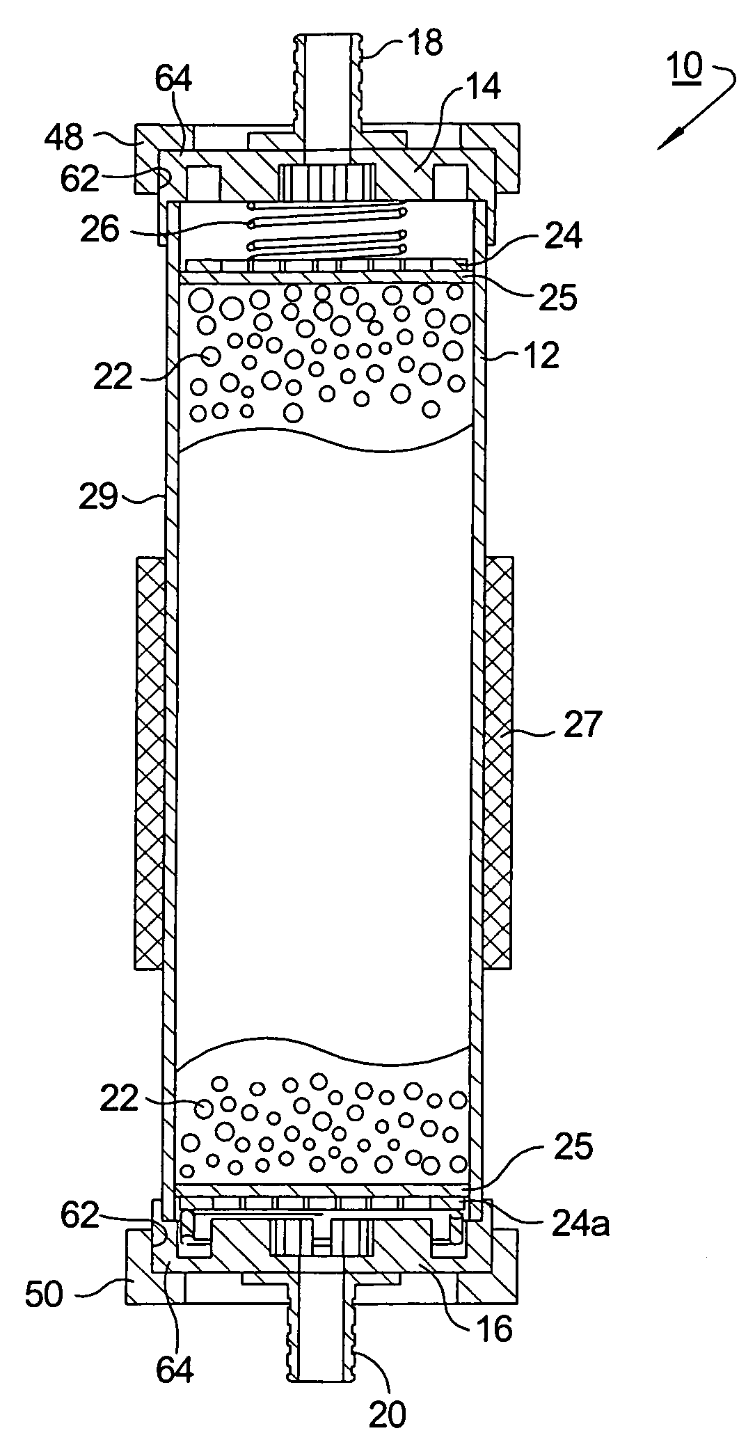
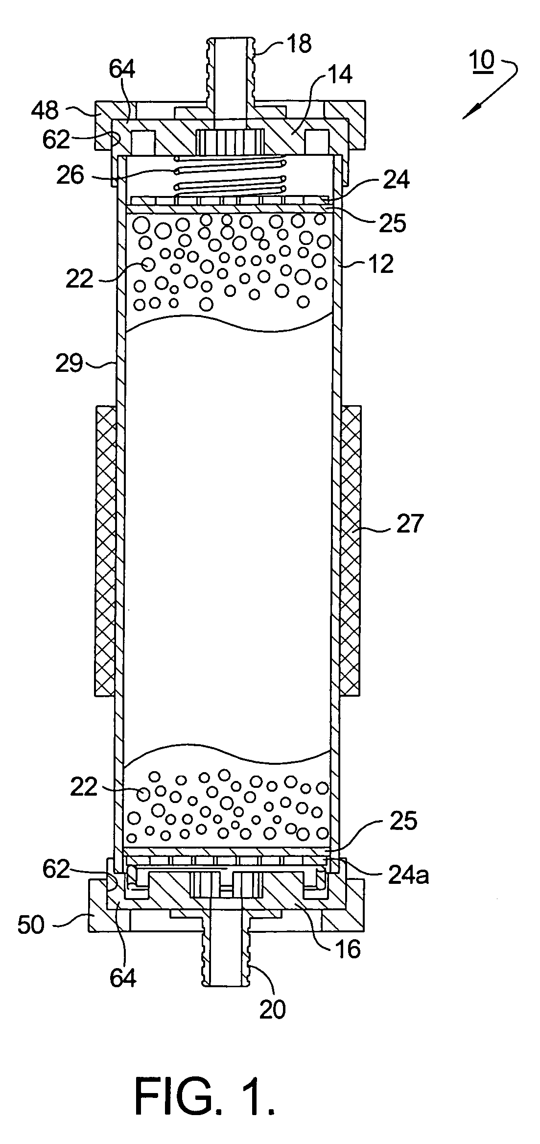
[0018]Referring to FIG. 1, an improved canister assembly 10 for adsorption of fuel vapors in accordance with the invention comprises an elongate housing 12 having first and second end caps 14,16, each end cap including a tubular connector 18,20 for connection of assembly 10 to hose or pipe as described below. Preferably, housing 12 is formed by linear extrusion in known fashion of a thermoplastic polymer, for example, a polyolefin such as polypropylene, or a polyamide such as nylon. Preferably, end caps 14,16 are formed by injection molding of similar polymeric materials such that the end caps may be sealingly joined to the housing in known fashion as by adhesives, laser welding, spin welding, or the like. Alternatively, housing 12 and / or end caps 14,16 may be formed of a corrosion-resistant metal such as a stainless steel and may be welded together in known fashion to form assembly 10.

[0019]An amount of a vapor-adsorbent material 22 is disposed within housing 12 such that vapors en...


PUM


Abstract

An evaporative emissions control canister for adsorbing fuel vapors from a fuel tank on a marine vessel. The canister comprises a polymeric extruded housing that may be formed to any desired length or cut from extruded stock. Identical end caps having tubing connectors are bonded to opposite ends of the housing, defining an inlet and an outlet. Marine-grade pelletized activated carbon is disposed within the housing between porous slidable plates that are spring loaded against the end caps to pack the carbon tightly against the housing walls. Mounting brackets at each end are rotatably attached to the end caps so that opposite ends of the assembly may be attached to different surfaces of the vessel's hull, thus relieving stress which might be introduced into the assembly. Preferably, the assembly is wrapped in a fire retardant material.

Description

TECHNICAL FIELD[0001]The present invention relates to adsorption of hydrocarbon vapors; more particularly, to carbon-containing canisters for adsorbing fuel vapors displaced from fuel tanks during diurnal temperature changes; and most particularly, to an improved evaporative emissions canister suitable for use in boats having fixed onboard fuel tanks.BACKGROUND OF THE INVENTION[0002]Canisters for adsorptive control of fuel vapors are well known in the automotive arts. A typical automotive emissions control canister comprises a housing having an inlet and outlet and a chamber for holding a charge of activated carbon. The inlet is connected to the headspace in the vehicle's fuel tank and the outlet is vented to atmosphere. In addition, the canister has a purge tube located on the inlet end of the canister which is connected to a vacuum source on the engine. When the fuel vapor volume expands thermally in the tank, the displaced fuel vapors are adsorbed by the activated carbon bed. Whe...

Claims


Application Information

Patent Timeline
Patent Type & Authority Patents(United States)
IPC IPC(8): F02M33/02B01D53/04
CPCB63B11/04B63J2/02F02M25/0854F02B61/04
Inventor BEGLEY, CHRIS C.COVERT, CHARLES H.
Owner DELPHI TECH IP LTD
Why Eureka
Try Eureka