Eureka AIR delivers breakthrough ideas for toughest innovation challenges, trusted by R&D personnel around the world.

Transmission line coding method, transmission line decoding method, and apparatus therefor

a transmission line and coding technology, applied in the direction of coding, error correction/detection using convolutional codes, instruments, etc., can solve the problems of complex system configuration, degrading speech quality, and muted sound, so as to reduce the amount of arithmetic operations in decoding, reduce the amount of redundant bits, and suppress the increase in bit rate

Inactive Publication Date: 2009-01-13
PANASONIC CORP
View PDF18 Cites 5 Cited by
  • Summary
  • Abstract
  • Description
  • Claims
  • Application Information

AI Technical Summary

Benefits of technology

[0007]An object of the invention is to provide a transmission line coding method, a transmission line decoding method, and an apparatus using these method, which are capable of assuring decoding quality with a small number of redundant codes and suppressing the degradation of the quality of signals such as a decoded sound signal.

Problems solved by technology

However, in the conventional communications system mentioned above, sounds are muted for the duration of a frame where a transmission error has taken place.
This results in interruption of sounds in the meantime thus degrading the speech quality.
This results in a complicated system configuration.

Method used


Image

  • Transmission line coding method, transmission line decoding method, and apparatus therefor
  • Transmission line coding method, transmission line decoding method, and apparatus therefor
  • Transmission line coding method, transmission line decoding method, and apparatus therefor

Examples


first embodiment

[0044]A first embodiment shows an exemplary configuration of an audio encoder and an audio decoder for coding / decoding sound signals as an example applied for a transmission line coding method and a transmission line decoding method according to the invention.

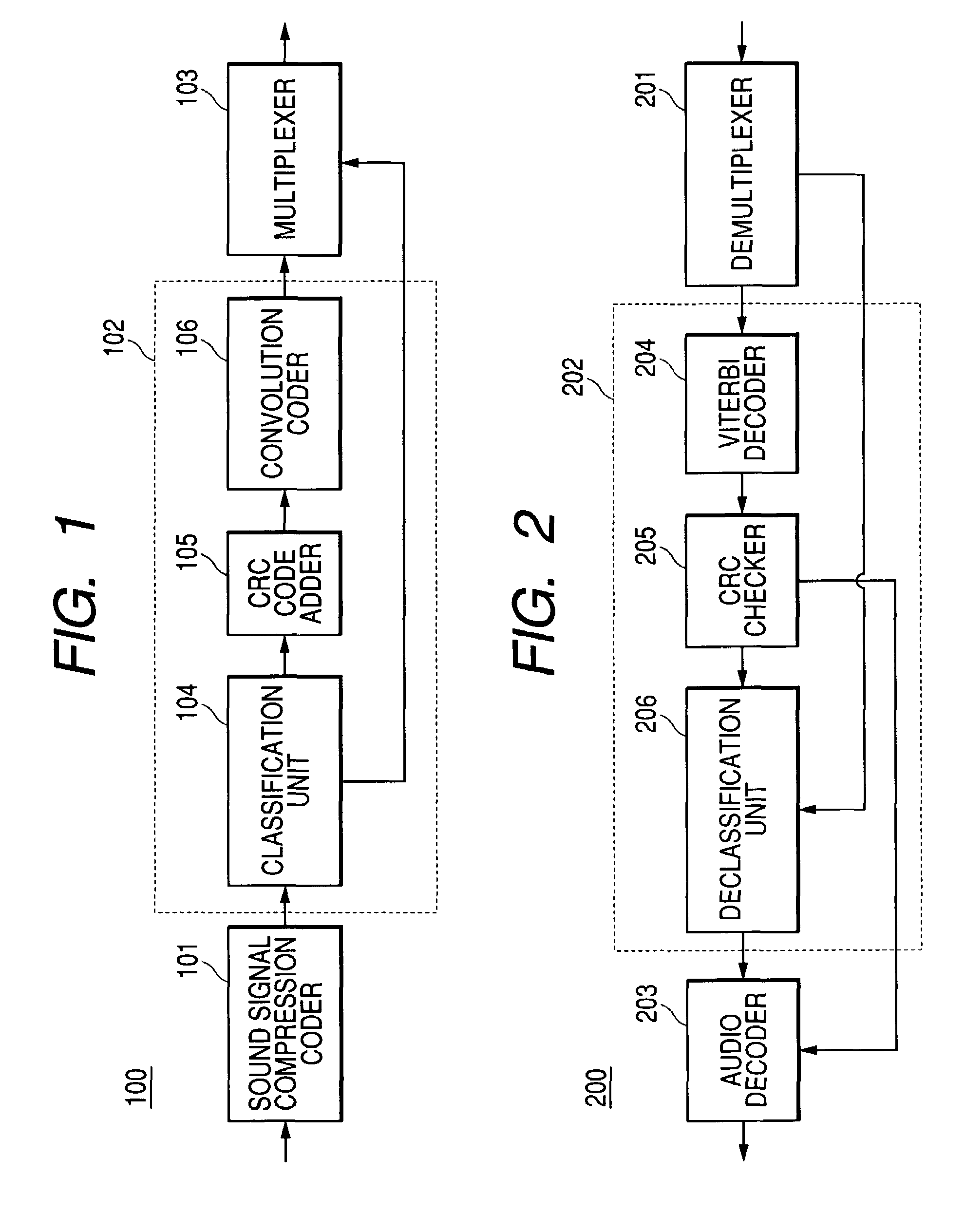
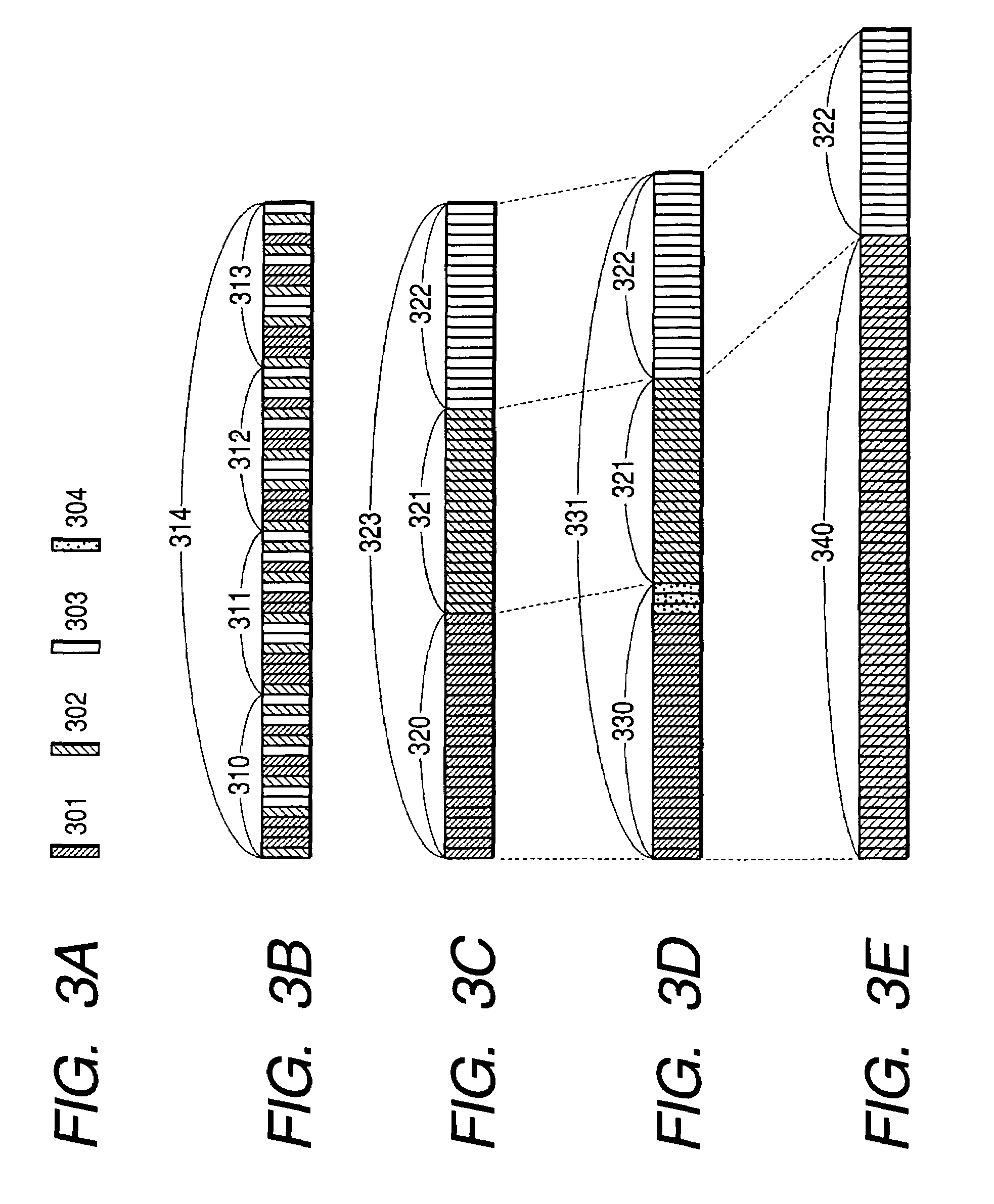
[0045]FIG. 1 is a block diagram showing the configuration of an audio encoder according to the first embodiment of the invention. An audio encoder 100 has an sound signal compression coder 101 for converting an input sound signal to low-bit-rate compressed frame data consisted of a coded bit stream, a transmission line coder 102 for encoding the compressed frame data per transmission frame, and a multiplexer 103 for adding preamble information and synchronization signals to the coded transmission frame to form a bit stream.

[0046]The transmission line coder 102 has a classification unit 104 for grouping each bit of the compressed frame data output from the sound signal compression coder 101 into plural classes in descending orde...

second embodiment

[0066]A second embodiment is an example of applying a transmission line coding method and a transmission line decoding method according to the invention to a digital wireless microphone system.

[0067]FIG. 6 is a block diagram showing the configuration of a transmitter of a digital wireless microphone system according to the second embodiment of the invention. A transmitter 500 has a microphone 510, an amplifier 520, an A / D converter 530, an audio encoder 540, a digital modulator / RF amplifier 550, and a transmitting antenna 560. The audio encoder 540 has a sound signal compression coder 541 and a transmission line coder 542.

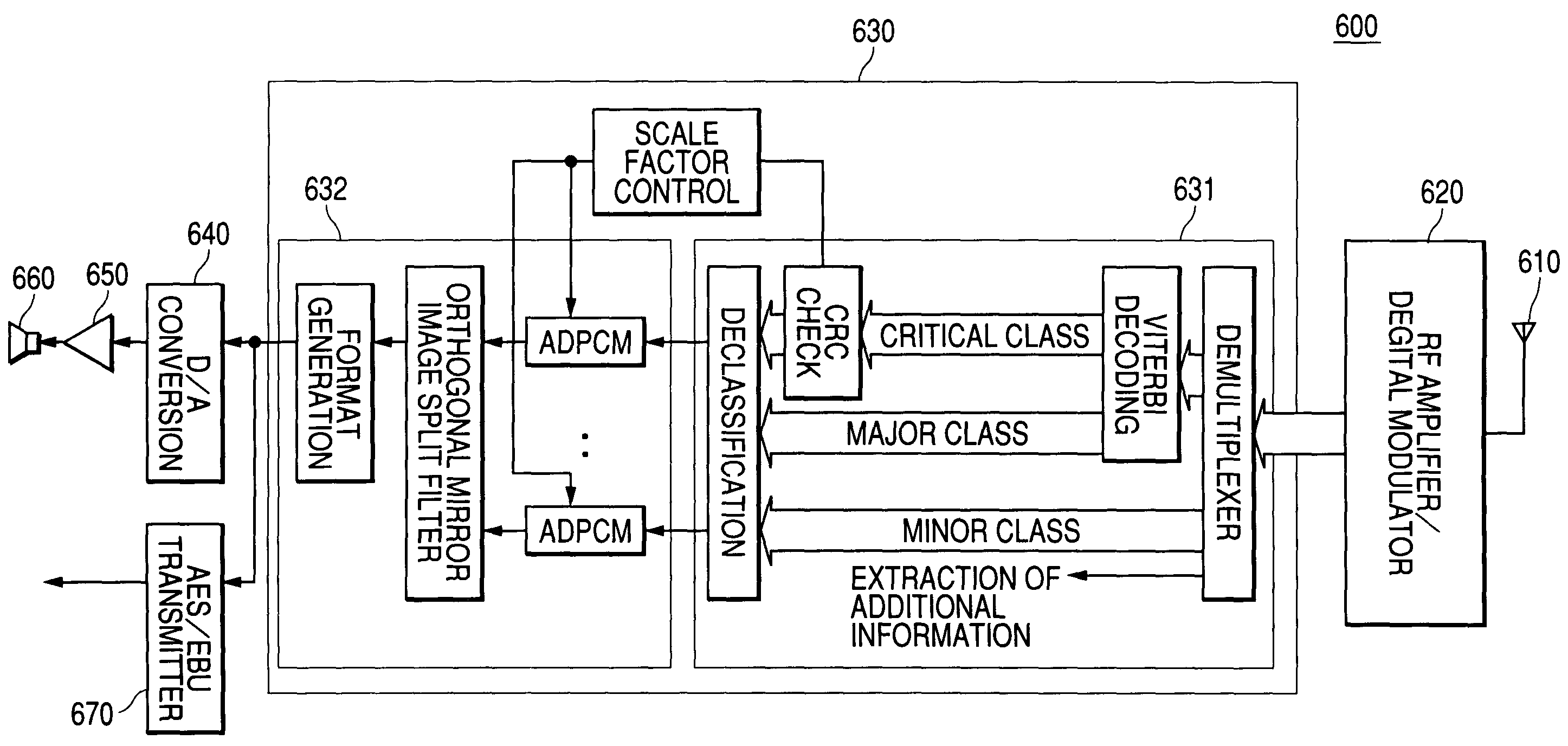
[0068]FIG. 7 is a block diagram showing the configuration of a receiver of a digital wireless microphone system according to the second embodiment of the invention. A receiver 600 has an RF amplifier / digital demodulator 620, an audio decoder 630, a D / A converter 640, an amplifier 650, a speaker 660, and an AES / EBU transmitter 670. The audio decoder 630 has a transm...


PUM


Abstract

An audio encoder converts an input sound signal into a plurality of compressed frame data pieces in an sound signal compression coder, determines the importance of each bit in a classification unit of a transmission line coder based on the decoding quality in the presence of a transmission error, and classifies the bits into a plurality of classes. The audio encoder selects one of the three types of processing including convolution coding and addition of CRC check codes, convolution coding only, and no coding, in descending order of importance in the presence of a transmission error for each class. Then, the audio encoder adds preamble information and a synchronization signal in a multiplexer to generate a bit stream. It becomes possible to suppress degradation of a decoded sound signal without additional redundant bits.

Description

BACKGROUND OF THE INVENTION[0001]1. Field of the Invention[0002]The present invention relates to a transmission line coding method and a transmission line decoding method for line coding / decoding sound signals used by electronic equipments, and an apparatus which uses these methods.[0003]2. Description of the Related Art[0004]There have been known a transmission line coding method and a transmission line decoding method for line coding / decoding sound signals defined in RCR-STD28 (PHS standards) of the Association of Radio Industries and Businesses (ARIB). FIG. 8 is a block diagram showing the key configuration of a communications system which performs this type of line coding / decoding.[0005]The sending party has an ADPCM encoder 701 and a CRC code adder 702. The sending party adds CRC check code bits to all of sound signals subjected to compression coding by way of the ADPCM mode per transmission frame and then transmits. The receiving party has a CRC code checker 703 for detecting ...

Claims


Application Information

Patent Timeline
Patent Type & Authority Patents(United States)
IPC IPC(8): H03M13/00G10L19/00G10L19/005G10L19/02H03M7/38H03M13/23H03M13/35H04B14/06H04L1/00
CPCH04L1/0041H04L1/0059H04L1/0061H04L1/007
Inventor BANBA, YUTAKA
Owner PANASONIC CORP
Why Eureka
Eureka Blog
Learn More