Supercharge Your Innovation With Domain-Expert AI Agents!

Timing driven logic block configuration

a logic block and timing technology, applied in the field of integrated circuits, can solve the problems of insufficient information on block delay information, inaccurate signal delay and block delay information, and difficulty in configuration and/or optimization of logic blocks, and dsp blocks particularly, to achieve the effect of improving performan

Active Publication Date: 2009-01-13
XILINX INC
View PDF6 Cites 17 Cited by
  • Summary
  • Abstract
  • Description
  • Claims
  • Application Information

AI Technical Summary

Benefits of technology

[0009]The present invention provides a solution for configuring and / or optimizing a logic block of a programmable logic device (PLD) in a timing driven manner. One embodiment of the present invention can include a method of configuring a logic block of a PLD during physical implementation of a circuit design. An exemplary embodiment of the present invention can be used to configure and / or optimize logic blocks that have portions which can be selectively registered. The method can include identifying a logic block of the PLD that is located on a critical path, and, for each of a plurality of selectively registerable portions of the logic block, computing input slacks and output slacks based upon potential register usage within the logic block. The method further can include determining register usage for the logic block by maximizing a function which depends upon a measure of worst case slack for pipeline stages, thereby improving performance with respect to timing.
[0012]In yet another aspect of the invention, the determining step can include defining a measure of worst case slack for a first pipeline stage as minimizing a function which depends upon a measure of input slack and a measure of output slack for each input port of the logic block having an available register. The determining step also can include defining a measure of worst case slack for a second pipeline stage as minimizing a function which depends upon a measure of input slack and a measure of output slack for internal logic of the logic block having an available register. The determining step further can include defining the measure of worst case slack for a third pipeline stage as minimizing a function which depends upon a measure of input slack and a measure of output slack for each output port of the logic block having an available register.

Problems solved by technology

During synthesis, however, accurate signal delay and block delay information has not yet been determined.
Without the availability of timing information, configuration and / or optimization of logic blocks, and particularly DSP blocks, can be difficult.

Method used


Image

  • Timing driven logic block configuration
  • Timing driven logic block configuration
  • Timing driven logic block configuration

Examples


Embodiment Construction

[0021]While the specification concludes with claims defining the features of the invention that are regarded as novel, it is believed that the invention will be better understood from a consideration of the description in conjunction with the drawings. As required, detailed embodiments of the present invention are disclosed herein; however, it is to be understood that the disclosed embodiments are merely exemplary of the invention, which can be embodied in various forms. Therefore, specific structural and functional details disclosed herein are not to be interpreted as limiting, but merely as a basis for the claims and as a representative basis for teaching one skilled in the art to variously employ the inventive arrangements in virtually any appropriately detailed structure. Further, the terms and phrases used herein are not intended to be limiting but rather to provide an understandable description of the invention.

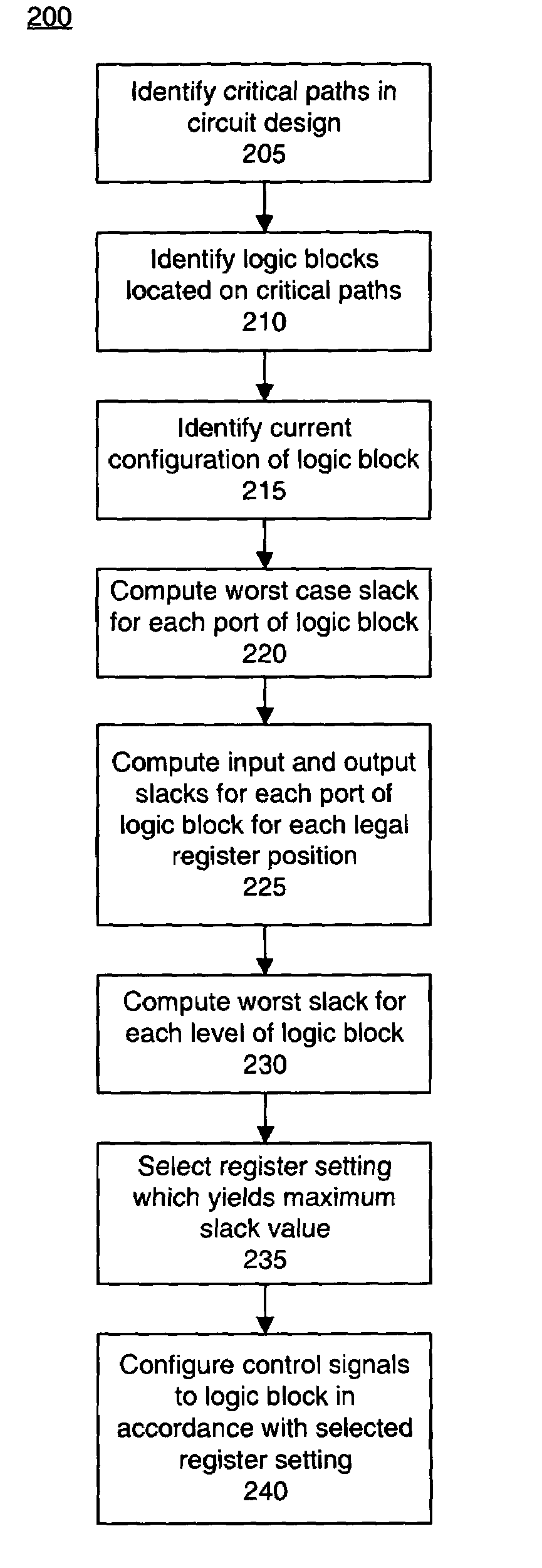
[0022]Embodiments of the present invention provide solutions for o...


PUM


Abstract

A method of configuring a logic block of a programmable logic device (PLD) during physical implementation of a circuit design, wherein ports of the logic block are selectively registered, can include identifying the logic block of the PLD, wherein the logic block is located on a critical path. For each of a plurality of selectively registerable portions of the logic block, the method can include computing input slacks and output slacks based upon potential register usage within the logic block. The method further can include determining register usage for the logic block by maximizing a function which depends upon a measure of worst case slack for pipeline stages.

Description

BACKGROUND[0001]1. Field of the Invention[0002]The present invention relates to the field of integrated circuits and, more particularly, to configuring logic blocks of programmable logic devices.[0003]2. Description of the Related Art[0004]Programmable logic devices (PLD's) such as field programmable gate arrays (FPGA's) can include an assortment of different types of components such as memories, central processing units, and the like. Increasingly, “black boxes”, also referred to as logic blocks, have been introduced into these devices to enhance application specific performance. One type of “black box” is, for example, a digital signal processor (DSP) block. Traditionally, logic block performance, and particularly DSP block performance, has been optimized during the synthesis phase of circuit design. During synthesis, a Hardware Description Language (HDL) design definition of a circuit is processed to generate the logical or physical representation of the circuit design for the ta...

Claims


Application Information

Patent Timeline
IPC IPC(8): G06F17/50
CPCG06F17/5054G06F30/34
Inventor SUNDARARAJAN, PRIYAKRISHNAMURTHY, SRIDHAR
Owner XILINX INC
Features
  • R&D
  • Intellectual Property
  • Life Sciences
  • Materials
  • Tech Scout
  • Unparalleled Data Quality
  • Higher Quality Content
  • 60% Fewer Hallucinations
Learn More