Device and method for analyzing a materials library

a material library and device technology, applied in the direction of optical radiation measurement, color/spectral property measurement, instruments, etc., can solve the problem of speeding up the determination of materials suitable for a specific application, and achieve the effect of speeding up the determination of materials

Inactive Publication Date: 2009-01-20
ROBERT BOSCH GMBH
View PDF24 Cites 4 Cited by
  • Summary
  • Abstract
  • Description
  • Claims
  • Application Information

AI Technical Summary

Benefits of technology

[0005]The device of the present invention for analyzing a materials library has the advantage that the elements of the materials library may be tested with respect to their properties simultaneously with a plurality of, in particular, spectroscopic methods. This results in greatly speeding up the determination of a material suitable for a specific application. Through the use of the materials library, the device of the present invention is designed for the implementation of a high throughput method in which the suitable material is to be determined according to combinatory chemical methods.
[0008]The clarification of the particular reaction mechanisms simultaneously with the determination of a change in absorption representing a sensor signal makes a targeted further development of materials possible.
[0016]It is advantageous in particular to position at least one wavelength-sensitive mirror both in front of and behind the materials library so that radiation of different wavelengths emitted by at least two radiation sources is combined into one bundle of rays in front of the materials library and may be split again as a function of wavelength or frequency behind the materials library. It is thus possible in a convenient manner to transmit a radiation beam onto or through the materials library using radiation from a plurality of frequency ranges in parallel and simultaneously. The wavelength-sensitive mirrors are formed, for example, from a heat reflecting filter that reflects infrared radiation and transmits visible light.

Problems solved by technology

This results in greatly speeding up the determination of a material suitable for a specific application.

Method used


Image

  • Device and method for analyzing a materials library
  • Device and method for analyzing a materials library

Examples


Embodiment Construction

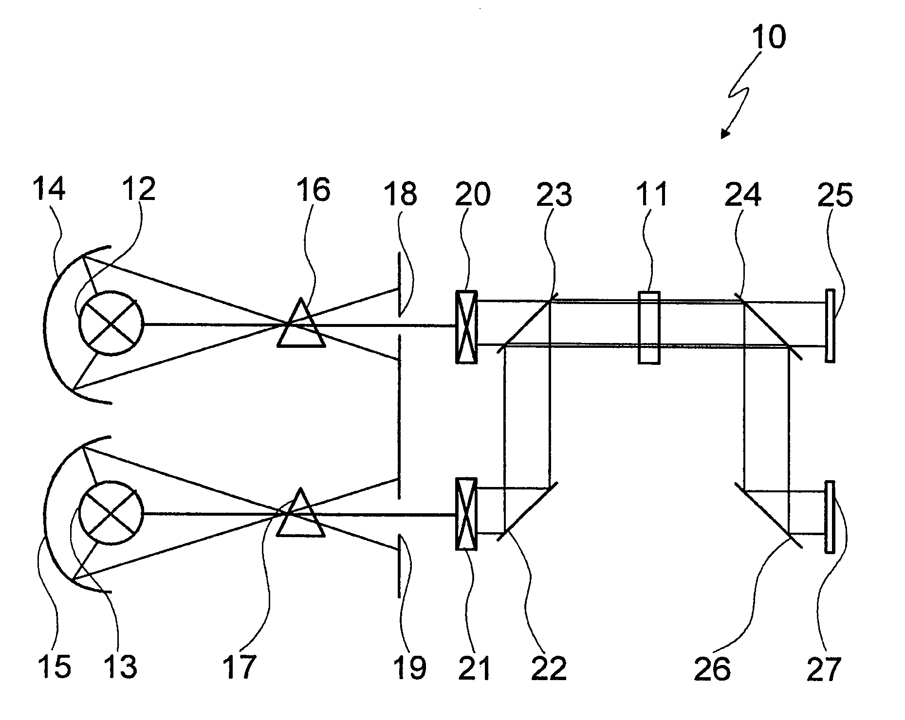
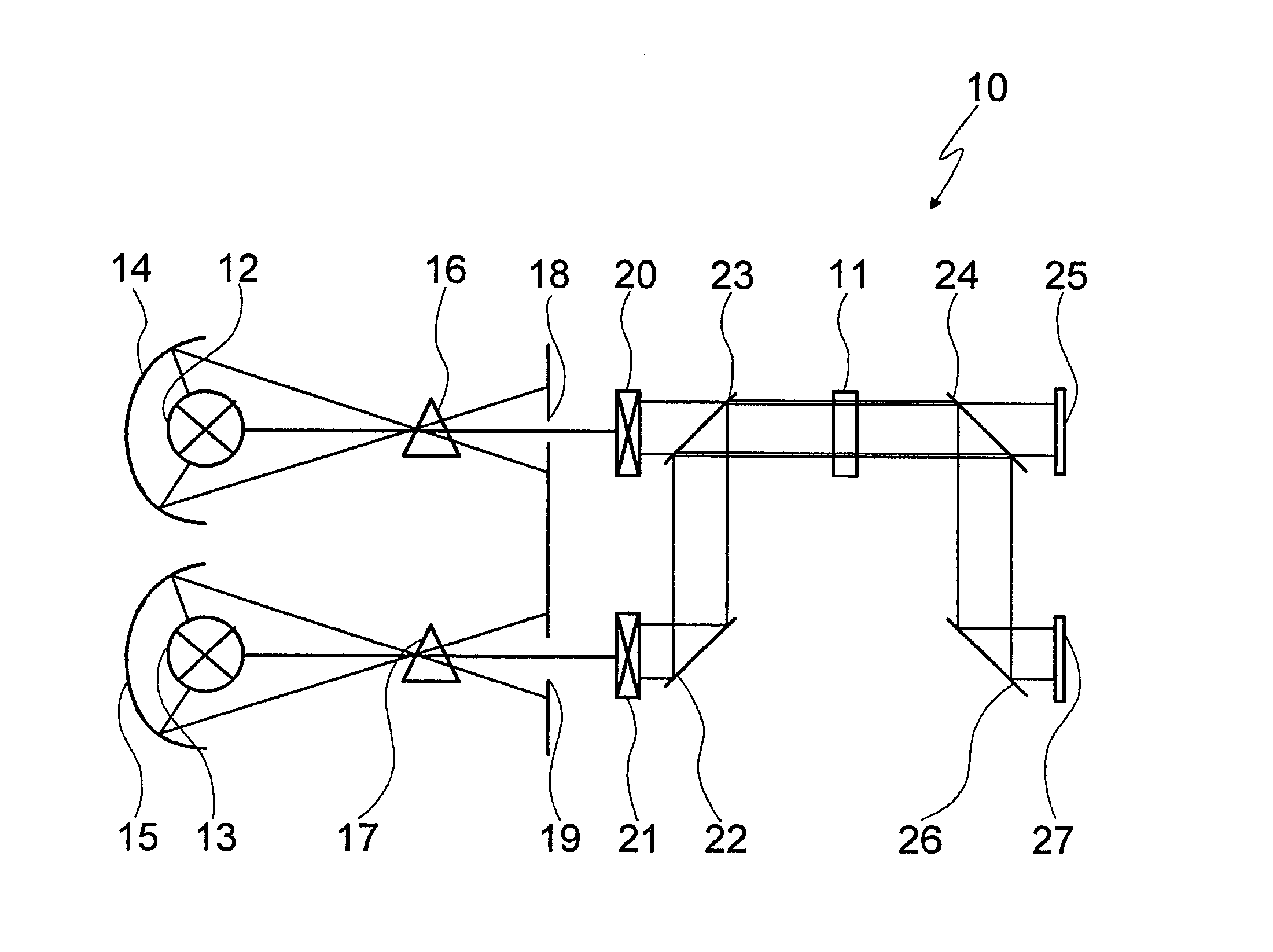
[0023]The FIGURE shows a device 10 for analyzing a materials library 11, which in the present case is made up of a plurality of elements or substances, each of which being usable as an optical sensor and are here situated on a combinatory substrate.

[0024]Device 10 includes two radiation sources 12 and 13, a reflection mirror 14 and 15, respectively being assigned to each of them. Radiation source 12 emits infrared radiation and radiation source 13 emits visible light.

[0025]Positioned downstream from radiation sources 12 and 13 is one monochromator 16 and 17, respectively, which selects radiation of a specific wavelength from the frequency spectrum emitted by radiation sources 12 and 13. A gap 18 and 19, respectively, is located behind monochromatic illuminators 16 and 17, the radiation from the particular radiation source being transmitted through the gap and then striking an optical system 20 and 21, respectively. Each of optical systems 20 and 21 includes a plurality of lenses, wh...


PUM

PropertyMeasurementUnit
infrared wavelength rangeaaaaaaaaaa
Raman wavelength rangeaaaaaaaaaa
UV wavelength rangeaaaaaaaaaa

Abstract

A device for analyzing a materials library includes at least one radiation source for electromagnetic radiation, which is positioned in front of the materials library, and at least two flat detectors operating in parallel, which are operable using high-sensitivity resolution and of which one is sensitive to electromagnetic radiation of a first wavelength range and the other is sensitive to electromagnetic radiation of a second wavelength range. Moreover, a method for analyzing a materials library in which the materials library is simultaneously tested using at least two methods in which electromagnetic radiation of different wavelength ranges is used. The beam is split behind the materials library as a function of wavelength and is deflected in the direction of at least two flat sensors operating using high-sensitivity resolution.

Description

BACKGROUND INFORMATION[0001]In order to be able to develop materials that are used, for example, for sensors or also for catalysts, it is presently customary to use high throughput methods in which a materials library is created, the elements of which are tested with respect to properties of significance to the particular application. The elements or materials of the materials library are primarily tested for the desired target property. Thus in the case of resistive sensors, the material having the best resistance properties is determined, in the case of optical sensors, the optical absorption characteristics and in the case of catalysts, substance conversion is analyzed.[0002]For example, for the development of an optical sensor that changes color under the influence of a gas, it is known from common practice to irradiate a materials library using visible light and to analyze it by spectroscopy using a corresponding detector, which is sensitive to this wavelength range.[0003]Moreo...

Claims


Application Information

Patent Timeline
Patent Type & Authority Patents(United States)
IPC IPC(8): G01J5/02G01N21/31
CPCG01N21/3151
Inventor SCHEYING, GERDKATZENBERGER, STEFFENBRINZ, THOMASJOCKEL, JOERG
Owner ROBERT BOSCH GMBH
Why Eureka
Try Eureka