Control devices for a booster brake system of a vehicle and method for operating a booster brake system of a vehicle
- Summary
- Abstract
- Description
- Claims
- Application Information
AI Technical Summary
Benefits of technology
Problems solved by technology
Method used
Image
Examples
first embodiment
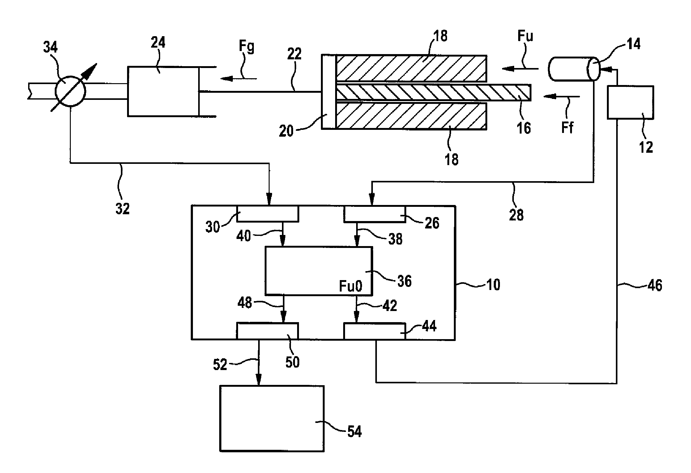
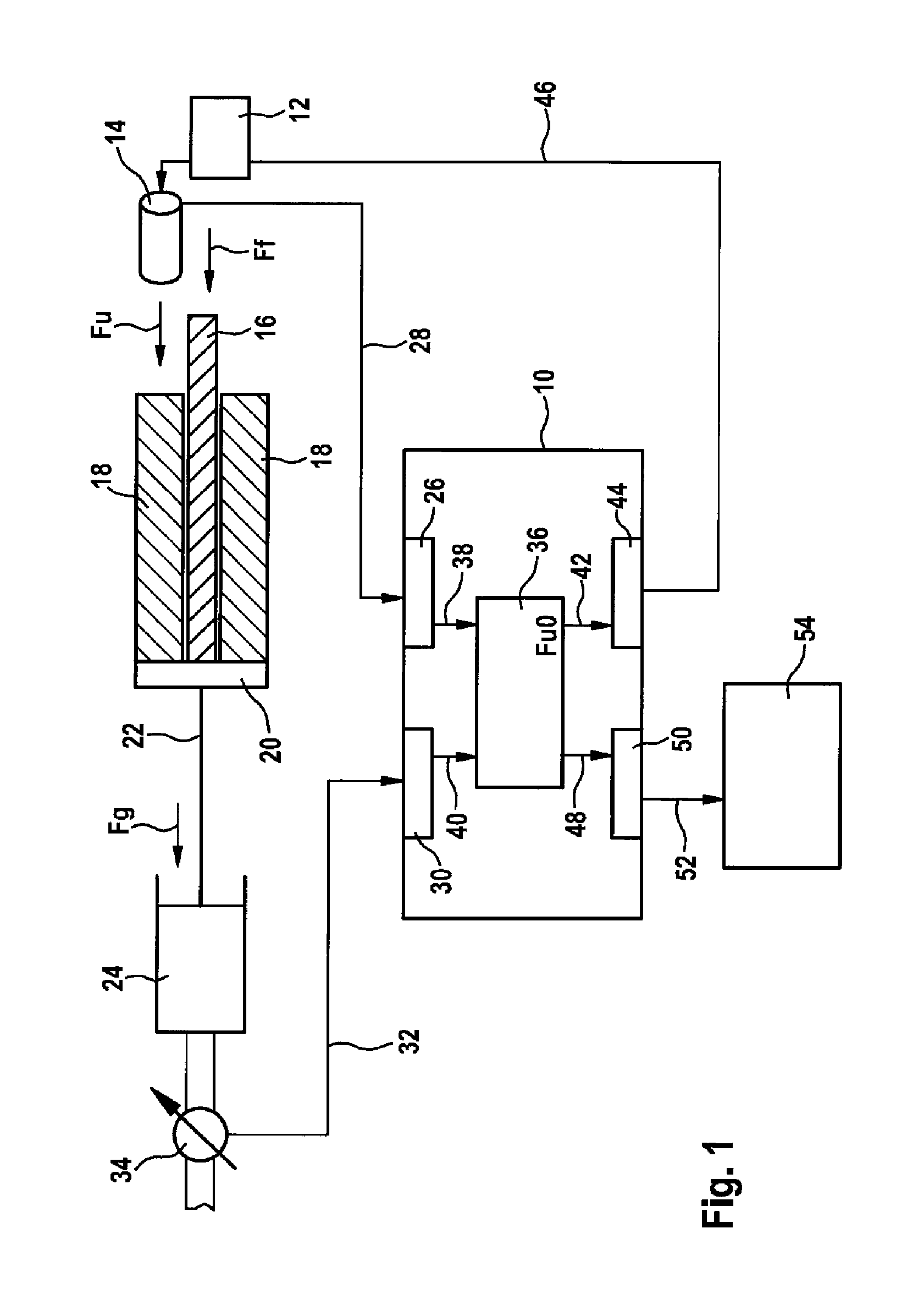
[0020]FIG. 1 is a schematic illustration of the control device.
[0021]The schematically represented control device 10 is used in a vehicle with a booster brake system. The booster brake system (only partially illustrated) has an activation element 12 such as, for example, a brake pedal. By means of the activation element 12, a driver can activate the brake system in order to brake at least one wheel of the vehicle using the control device 10. In this context, the driver applies a driver braking force Ff to the activation element 12.
[0022]In order to relieve the driver of work during braking of the vehicle, the brake system is additionally equipped with a brake booster 14. The brake booster 14 is configured to supply an (additional) assistance force Fu for braking the vehicle. The brake booster 14 can be, for example, an electromechanical brake booster, an electric brake booster or a hydraulic brake booster. It is to be noted that the application of the control device 10 is not restri...
second embodiment
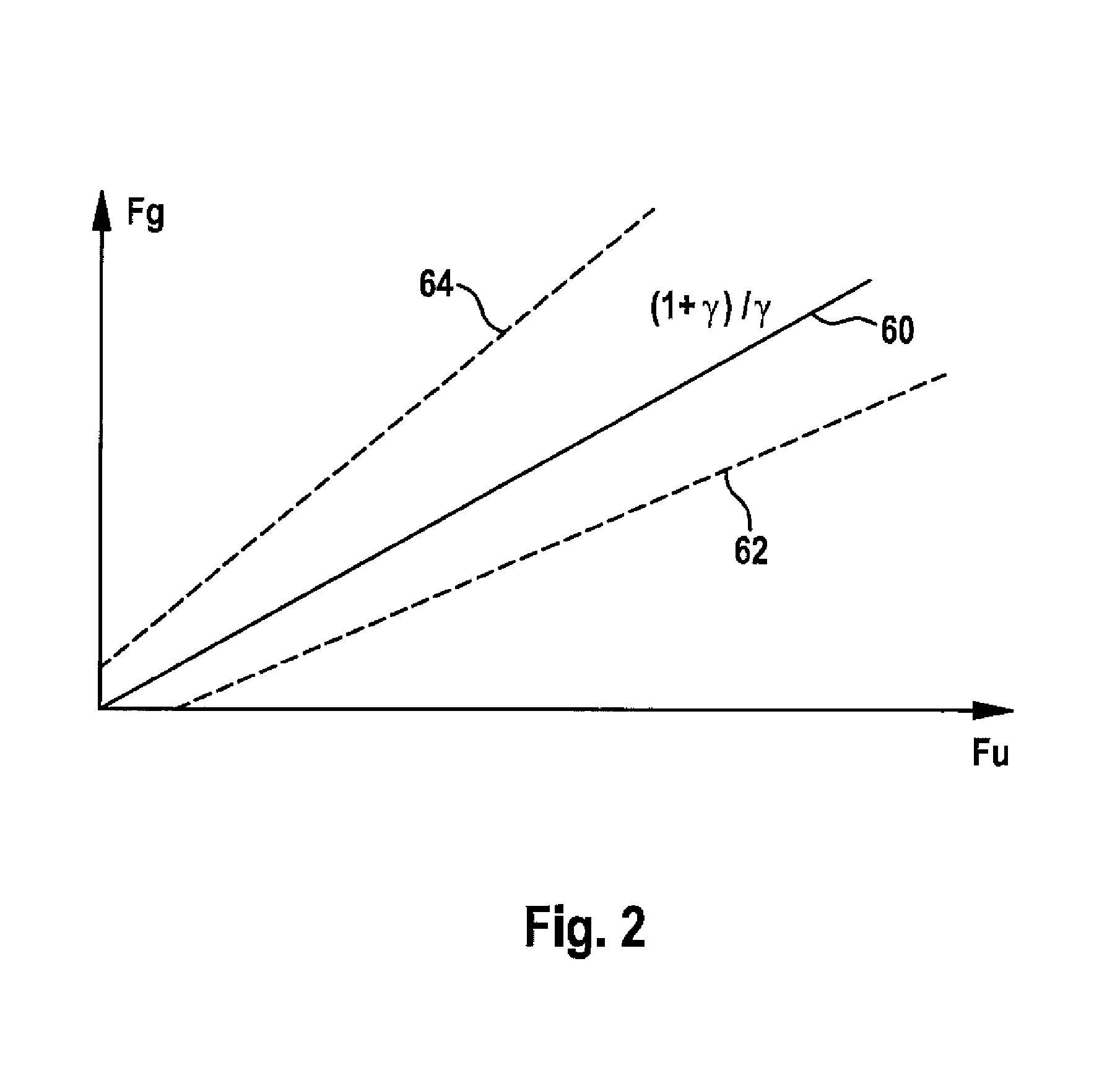
[0057]FIG. 2 shows a coordinate system for representing the control device. The abscissa of the coordinate system indicates a value range of the assistance force Fu which can be supplied to a first input device of the control device. The ordinate corresponds to a value range for the total braking force Fg which can be supplied to a second input device of the control device.
[0058]In the brake system (not outlined) which interacts with the control device in FIG. 2, the setpoint assistance force Fu0 is predefined to the brake booster as a function of the driver braking force Ff:
Fu0=f(Ff)=c(Ff)×Ff (Eq. 5)
[0059]In the text which follows, a closed-loop and open-loop control strategy which is easy to implement is used as the basis, in which strategy the following applies:
Fu0=γ×(Fg−Fu)=γ×Ff, (Eq. 9)
where γ is a constant factor. However, it is to be noted that the present invention is not restricted to checking for compliance with the setpoint assistance force Fu0 in this closed-loop and...
third embodiment
[0095]FIG. 5 is a schematic illustration of the control device.
[0096]The illustrated control device 70 for a booster brake system of a vehicle comprises an input device 72 for receiving an input signal 74 with a supplied variable relating to an assistance force of a brake booster 14 of the booster brake system (only partially outlined). The supplied variable comprises, for example, the assistance force, a motor current, a motor torque, a motor position, a temperature, a pressure value and / or a corresponding variable which represents a method of functioning of the brake booster 14.
[0097]The input device 72 outputs a signal 76, corresponding to the supplied variable, to an evaluation device 78 of the control device 70. The output device 78 is configured to compare the received variable (or the signal 76) relating to the assistance force with a predefined setpoint variable relating to the assistance force. The setpoint variable can be stored on the evaluation device 78. Likewise, the s...
PUM
 Abstract
Description
Claims
Application Information
 - R&D
- Intellectual Property
- Life Sciences
- Materials
- Tech Scout
- Unparalleled Data Quality
- Higher Quality Content
- 60% Fewer Hallucinations
Browse by: Latest US Patents, China's latest patents, Technical Efficacy Thesaurus, Application Domain, Technology Topic, Popular Technical Reports.
© 2025 PatSnap. All rights reserved.Legal|Privacy policy|Modern Slavery Act Transparency Statement|Sitemap|About US| Contact US: help@patsnap.com


