System and method for protecting a motor drive unit from motor back EMF under fault conditions

a technology protection system, which is applied in the direction of motor/generator/converter stopper, dynamo-electric converter control, ac motor stopper, etc., can solve the problems of damage to the capacitors of the dc link and/or switches of the inverter, the effect of back electromotive force generated during high-speed operation is automatically limited, and the generative potential of the motor will no longer be controlled

Inactive Publication Date: 2009-01-20
ROCKWELL AUTOMATION TECH
View PDF3 Cites 50 Cited by
  • Summary
  • Abstract
  • Description
  • Claims
  • Application Information

AI Technical Summary

Benefits of technology

[0013]In accordance with another aspect of the present invention, a motor drive unit protection system is disclosed that includes at least one switch configured to be connected between a motor drive unit and a plurality of motor leads of a motor driven by the motor drive unit. The motor drive unit protection system also includes a controller configured to monitor the motor drive unit or the motor to determine a fault condition indicative of the motor potentially operating as an uncontrolled generator. Upon determining the fault condition, the controller is configured to cause the at least one switch to connect the plurality of motor leads together to protect the motor drive unit from the motor when the motor is operating as a generator.

Problems solved by technology

Generally, the effects of the back EMF generated during high-speed operation are automatically limited by the applied DC link voltage.
However, should a fault arise while the motor is operating at high-speeds that causes the gate excitation to be removed from the controlled inverter switches, the generative potential of the motor will no longer be controlled.
This “reverse” current flow and the associated high voltage from PM motor may damage the capacitors of the DC link and / or switches of the inverter.
Therefore, the PM motor has the potential to damage or destroy the power electronics of the motor drive unit and may even create an unsafe condition in high kinetic energy applications.
However, such braking systems require additional system design and maintenance.
Furthermore, while these braking systems reduce the impact of a fault, they are unable to react to fault conditions quickly enough to stop the motor from injecting the “reverse” current flow back toward the motor drive unit.
As such, the components of the motor drive unit may still be damaged by being subjected to a significant voltage increase that occurs while the braking system attempts to control the motor.
However, the cost of high voltage DC link capacitors and high voltage inverter switches significantly increases the cost of the drive design.
Additionally, the use of high voltage silicon switches in the inverter significantly increases the losses incurred along the inverter and; thereby, decreases the power density and overall efficiency of the motor drive unit.

Method used


Image

  • System and method for protecting a motor drive unit from motor back EMF under fault conditions
  • System and method for protecting a motor drive unit from motor back EMF under fault conditions
  • System and method for protecting a motor drive unit from motor back EMF under fault conditions

Examples


Embodiment Construction

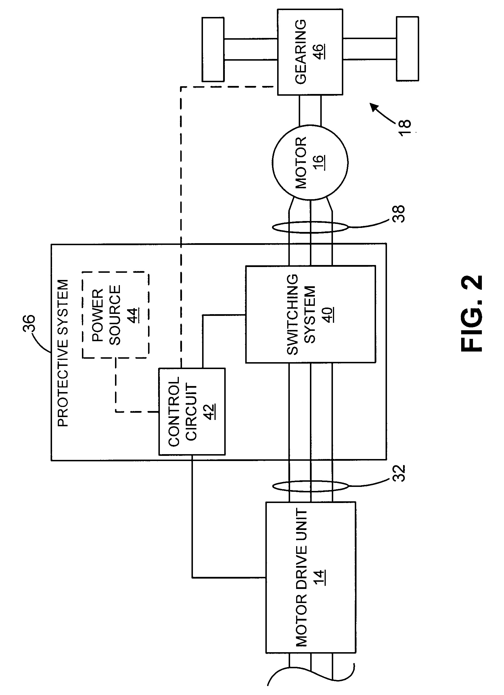
[0025]While the following description is generally directed to motor systems, it is contemplated that the following invention can be used with a wide variety of specific motors. For example, as will be described with respect to FIG. 2, it is contemplated that the invention may be used with vehicular power systems, such as hybrid vehicle systems, or many other motor systems.

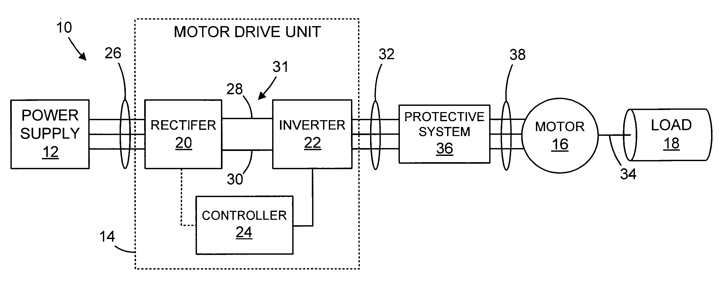
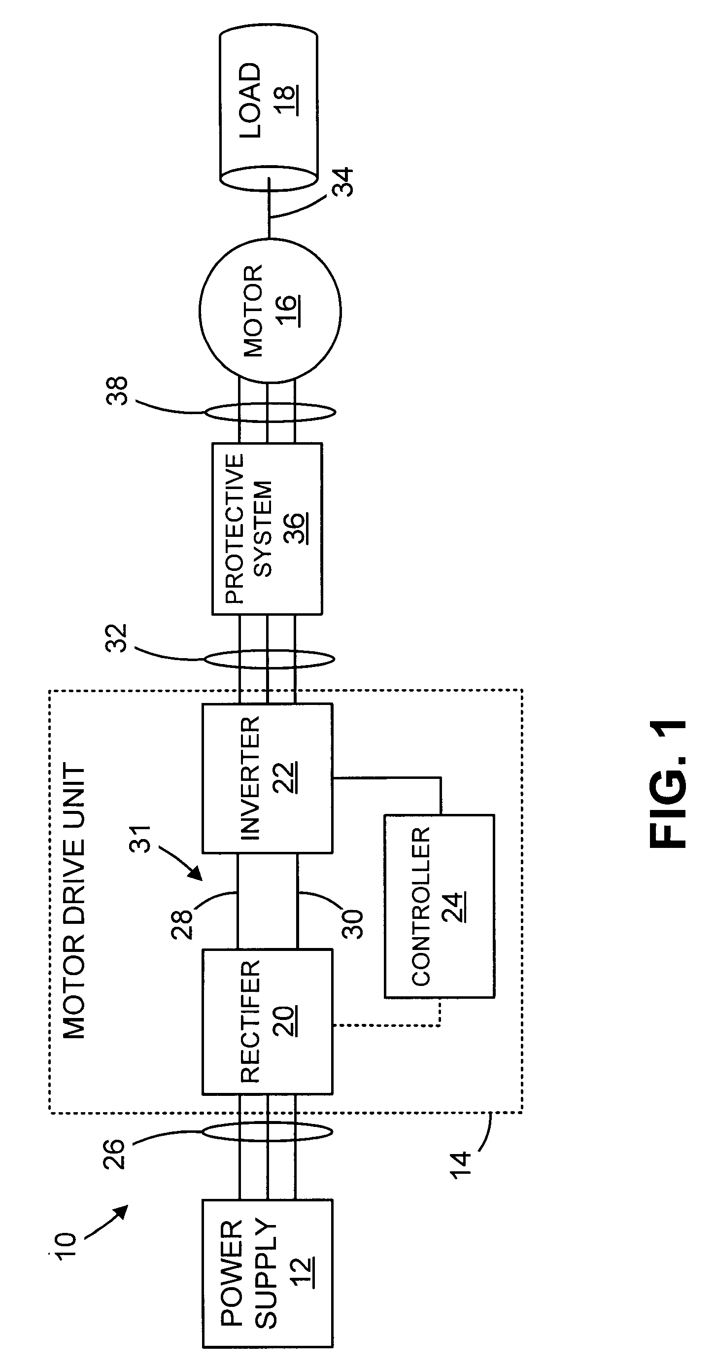
[0026]Referring now to FIG. 1, the present invention can be described in the context of a motor system 10. The motor system 10 generally includes a power supply 12, a motor drive unit 14, and a permanent magnet motor 16. The power supply 12 provides power to the motor drive unit 14 that, in turn, converts the power to a more usable form for the permanent magnet motor 16 that drives an associated load 18.

[0027]The motor drive unit 14 includes a variety of components, such as a rectifier 20, an inverter 22, and a controller 24. During operation, the power supply 12 provides three-phase AC power, for example, as rece...


PUM


Abstract

A system and method for protecting a motor drive unit from an associated motor includes a motor drive unit protection system. The motor drive unit protection system includes at least one switch configured to be connected between a motor drive unit and a plurality of motor leads of the motor driven by the motor drive unit. The motor drive unit protection system also includes a controller configured to monitor the motor drive unit or the motor to determine a fault condition indicative of the motor potentially operating as a generator. Upon determining the fault condition, the controller is configured to cause the at least one switch to connect the plurality of motor leads together to protect the motor drive unit from the motor when the motor is operating as a generator.

Description

CROSS-REFERENCE TO RELATED APPLICATIONS[0001]Not applicable.STATEMENT REGARDING FEDERALLY SPONSORED RESEARCH OR DEVELOPMENT[0002]Not applicable.BACKGROUND OF THE INVENTION[0003]The present invention relates generally to motor systems and, more particularly, to a system and method for controlling the effects of motor back electromotive force (EMF) on a motor drive unit. The present invention utilizes high-speed semiconductor switches to short the motor leads in the event of a fault condition. As such, the generative potential of the motor is contained and the motor drive unit is protected from the high voltage produced by the motor during high speeds.[0004]There are a variety of applications that require a motor to deliver constant power over a wide operational range. Permanent magnet (PM) synchronous motors have often been utilized in such applications because, by properly adjusting the combination of magnetic saliency and permanent magnet flux in the PM motor design, the resulting ...

Claims


Application Information

Patent Timeline
Patent Type & Authority Patents(United States)
IPC IPC(8): H02P1/26
CPCH02H7/1216H02P3/22H02P9/006
Inventor KASUNICH, JOHN M.PIXLER, DANIELCONCANNON, BRIAN T.MELFI, MICHAEL J.ROYAK, SEMYONHARBAUGH, MARK M.
Owner ROCKWELL AUTOMATION TECH
Why Eureka
Try Eureka