Eureka AIR delivers breakthrough ideas for toughest innovation challenges, trusted by R&D personnel around the world.

High-altitude capable wide velocity range flight velocity vector measurement probe and measurement system

a technology of vector measurement and high altitude, applied in the field of square pyramid type multi-hole pitot tube probe, can solve problems such as detection system malfunction, and achieve the effects of reducing the error in the mach number calculated by means of the mach table, high precision and good precision

Inactive Publication Date: 2009-01-20
JAPAN AEROSPACE EXPLORATION AGENCY
View PDF6 Cites 15 Cited by
  • Summary
  • Abstract
  • Description
  • Claims
  • Application Information

AI Technical Summary

Benefits of technology

[0008]It is an object of the present invention to provide a wide velocity range flight velocity vector measurement system which can solve the problem of the drop in precision seen in conventional systems using a square-pyramid type five-hole probe that is caused by the drop in atmospheric pressure that occurs in the case of aircraft flying at high altitudes that reach distances of up to 30 km from the surface of the earth, and which can thus prevent a drop in the measurement precision.
[0009]Furthermore, it is an object of the present invention to provide a method for eliminating the effects of detection fluctuations caused by the adhesion of water droplets, ice particles or dust in a wide velocity range flight velocity vector measurement system.
[0015]Since the present invention is devised so that Mach number calculations are performed by adding static pressure information obtained from static pressure holes that are newly added to the side surface parts of the pitot tube to the five sets of pressure information obtained by means of a conventional square pyramid type five-hole probe, a static pressure value that is substantially equal to the true static pressure surrounding the aircraft can be directly determined. Furthermore, since the difference between this pressure and the total pressure is a value that is larger than the difference from the pressure on the inclined surfaces of the square pyramid, the error in the Mach number that is calculated by means of the Mach table is reduced. Accordingly, highly precise flight Mach numbers that could not be obtained using conventional square pyramid type five-hole probes in high altitude ranges such as altitudes of 30 km can be obtained with good precision.
[0016]Furthermore, since the static pressure holes formed in the probe tube wall in the system of the present invention comprise a plurality of holes each respectively disposed at equal intervals centering on the three o'clock and nine o'clock position on a clock face display in the cross section of the tube, static pressure values that show no great variation in characteristics due to variations in the magnitude of the angle of attack or sideslip angle can be detected; this makes it possible to calculate Mach number values that show good precision. Furthermore, since the static pressure holes are disposed in positions located in front of the total pressure balance hole that do not overlap with the total pressure balance hole, static pressure values showing good precision that are not affected by the air flow that is discharged from the total pressure balance hole can be detected.
[0018]Moreover, by dividing a wide velocity range from low velocity to supersonic velocity into several velocity ranges, and determining the respective coefficients of the abovementioned approximation, it is possible to obtain Mach number showing good precision for a wide velocity range.
[0019]Furthermore, the wide velocity range flight velocity vector measurement system of the present invention is devised so that this system comprises means whereby signals based on pressure information from the total pressure hole, the four pressure holes in the square pyramid surfaces of the base part and the static pressure hole, which is taken in at the sampling interval, are compared with the values for the preceding frame, the data for the current frame is taken as the data for that point in time if the difference data does not exceed a threshold value, and the data for the preceding frame is read out and substituted for the data of the current frame in cases where it is judged that the difference data is an abnormal value that exceeds the threshold value. Accordingly, even if the detection holes are blocked by rain, snow, dust or the like, erroneous detection caused by such blockage can be effectively eliminated.

Problems solved by technology

However, in cases where these existing wide velocity range flight velocity vector measurement systems equipped with a square pyramid type five-hole probe are used, the following problem has been encountered: namely, although the velocity and attitude angle of aircraft flying at various attitude angles and velocities ranging from low velocity to high velocity at ordinary altitudes (12 km or lower) can be determined with a high degree of precision, the precision of the same system, in which the static pressure is determined by calculation from the pressure signals of the five holes, drops in the case of aircraft flying at high altitudes that may reach a distance of as much as 30 km from the surface of the earth, due to the fact that the atmospheric pressure is lower at such high altitudes.
Furthermore, in the case of pitot tube probes mounted on aircraft, the following problem has also been encountered: namely, instantaneous blockage of the detection holes during flight may be caused by water droplets or ice particles (under meteorological conditions such as rain and snow), or as a result of dust contained in the atmosphere contacting the probe, so that the detection system malfunctions.

Method used


Image

  • High-altitude capable wide velocity range flight velocity vector measurement probe and measurement system
  • High-altitude capable wide velocity range flight velocity vector measurement probe and measurement system
  • High-altitude capable wide velocity range flight velocity vector measurement probe and measurement system

Examples


Embodiment Construction

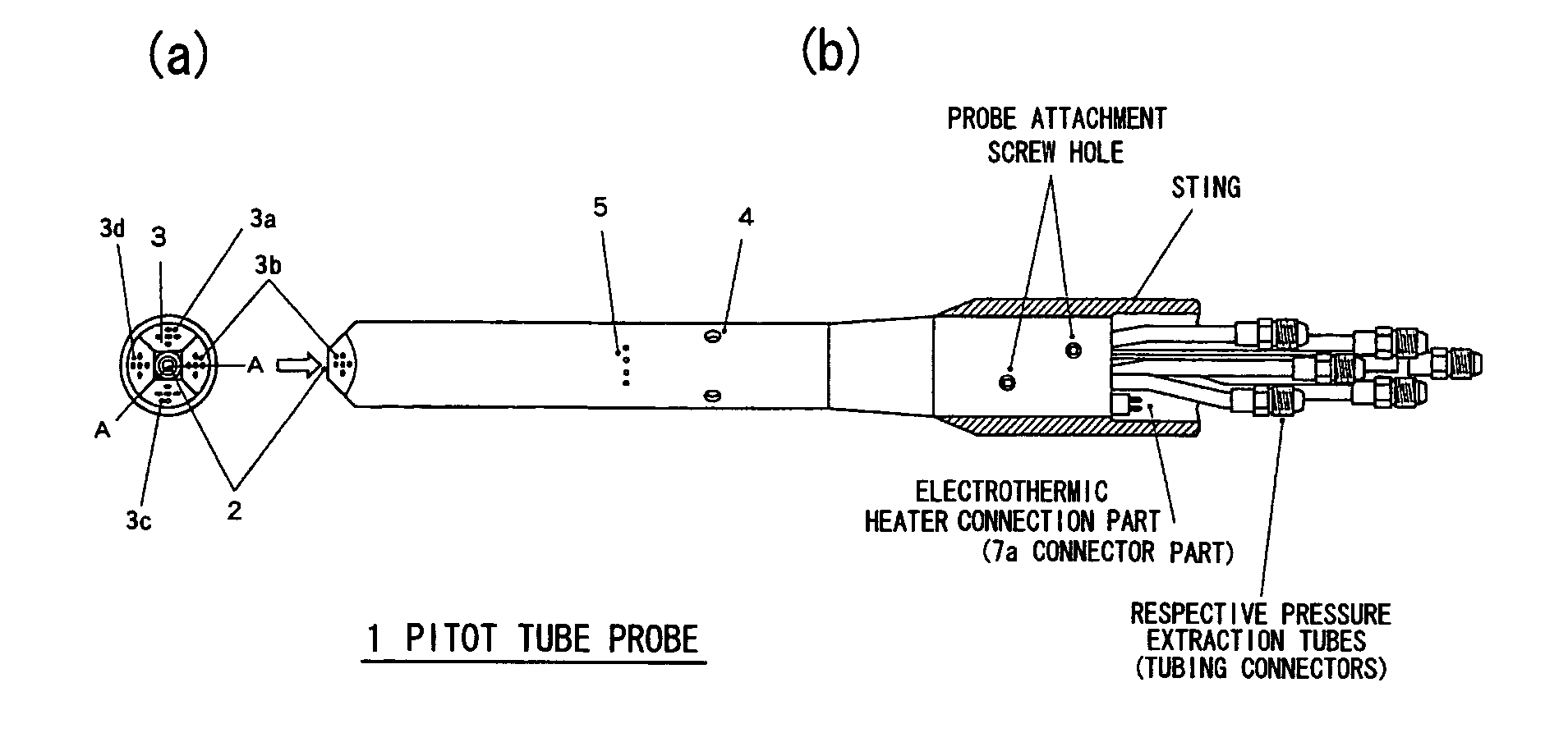
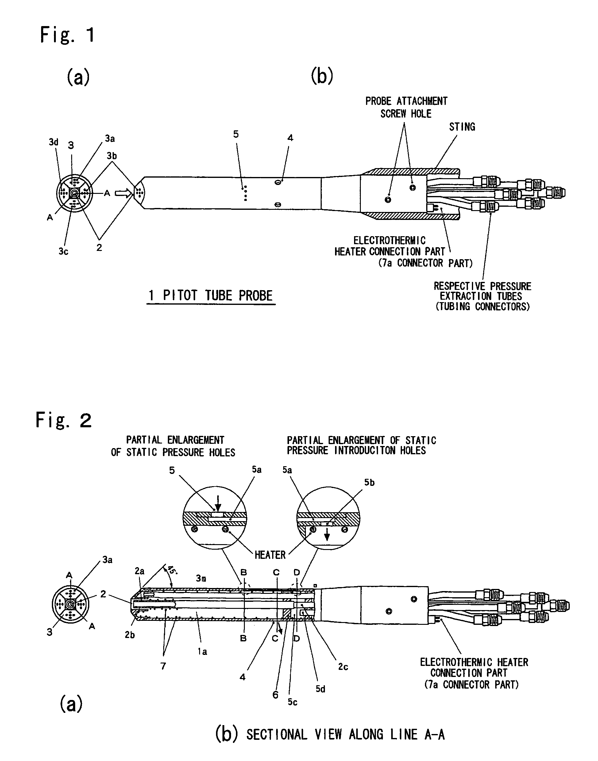
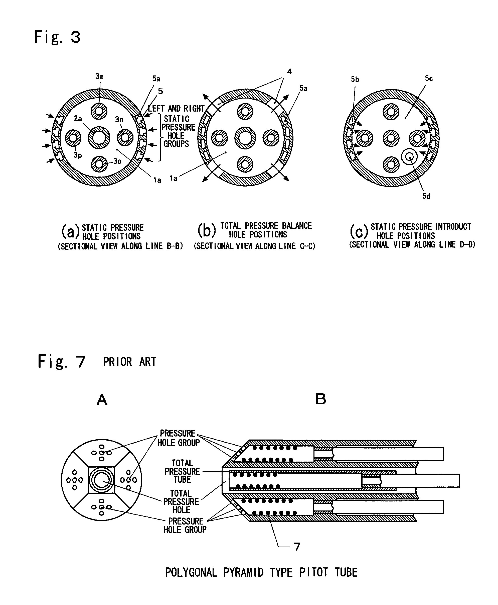
[0027]The present invention is characterized in that static pressure holes are formed in the tube wall surface of the probe, and the pressure values detected by these static pressure holes are added to the basic data that is used for Mach number calculation in order to prevent a drop in the precision of the flight Mach number calculated in the case of flight at high altitudes. The concrete structure of the present invention will be described with reference to FIGS. 1 through 3. FIG. 1 shows a front view and a side view of the six-hole probe of the present invention. FIG. 2 shows a front view of the same and a sectional side view of the tube part along line A-A, and also shows partial enlargements of the same. FIG. 3 shows sectional views along lines B-B, C-C and D-D. As is shown in these figures, a total pressure hole 2 is located in the central portion of the tip end of the pitot tube 1 and respective pressure holes 3a, 3b, 3c and 3d are formed in the square pyramid inclined surfac...


PUM


Abstract

It is an object of the present invention to solve the problem of a drop in precision in conventional systems using a square pyramid type five-hole probe due to the drop in atmospheric pressure in high altitude ranges, and to provide a wide velocity range flight velocity vector measurement system that can prevent a drop in measurement precision. Furthermore, it is also an object of the present invention to provide a method for eliminating the effects of detection fluctuations caused by adhering water droplets, ice particles or dust in a wide velocity range flight velocity vector measurement system. The flight velocity vector measurement probe of the present invention comprises means in which a static pressure hole is formed in the tube wall surface of the probe, so that a static pressure value is obtained from the pressure detected by this static pressure hole, the Mach number M is calculated on the basis of an equation approximated by a fourth-order polynomial of the static pressure / total pressure signal and the angle of attack, and in cases where an abnormal detection value is detected, this is replaced by the preceding detection value.

Description

BACKGROUND OF THE INVENTION[0001]1. Field of the Invention[0002]The present invention relates to a square pyramid type multi-hole pitot tube probe equipped with a total pressure hole located in the tip end part and four pressure holes located in the square pyramid surfaces of the base part, and a calculation system that can calculate flight velocity vectors such as the flight Mach number and the like, and the flight altitude, with high precision in a wide velocity range from low velocity to supersonic velocity at a high altitude.[0003]2. Description of the Related Art[0004]The present inventors previously developed a flight velocity vector measurement system using a pitot tube with a square pyramid type five-hole probe such as that shown in FIG. 7 (Japanese Patent Application Laid-Open No. 5-288761 “Flight Velocity Vector Detection System Using Polygonal Pyramid Type Pitot Tube Probe, and Polygonal Pyramid Type Pitot Tube Probe”, laid open on Nov. 2, 1993), and obtained patent right...

Claims


Application Information

Patent Timeline
Patent Type & Authority Patents(United States)
IPC IPC(8): G01P5/165G01P5/175
CPCG01C5/005G01P5/16G01P5/175G01P13/025
Inventor SHIGEMI, MASASHIKOIKE, AKIRAUENO, MAKOTOHIROTANI, TOMONARINAKAYA, TERUOMIWAKAI, HIROSHIIWATA, TORU
Owner JAPAN AEROSPACE EXPLORATION AGENCY
Why Eureka
Eureka Blog
Learn More