Method for operating a power plant

a power plant and power technology, applied in the direction of hot gas positive displacement engine plants, jet propulsion plants, machines/engines, etc., can solve the problems of significant temperature drop upstream of the air inlet of the engine, increase the net power output of the gas turboset, and reduce the power consumption of the compressor. , to achieve the effect of increasing the temperature of the atomization liquid, high overspray proportion, and high temperature differen

Inactive Publication Date: 2009-01-27
ANSALDO ENERGIA IP UK LTD
View PDF13 Cites 20 Cited by
  • Summary
  • Abstract
  • Description
  • Claims
  • Application Information

AI Technical Summary

Benefits of technology

[0014]According to one embodiment of the invention, the temperature in the inflow duct downstream of the atomization device is used as control variable for the control circuit. This is an eminently suitable way of extending the operating range of the water injection to ambient conditions in which there would otherwise be a likelihood of ice forming in the air inlet of the engine.
[0018]According to a second embodiment, the temperature control is operated as a limit value control. When a lower limit value for the temperature measured in the inflow duct, at which for example the formation of ice can no longer be ruled out, is reached, the temperature of the atomization liquid is increased.
[0019]In both embodiments, it is highly advantageous also to measure the temperature of the atomization liquid and for this temperature to be limited to an upper limit value which is, for example, a safety margin below the boiling point of the atomization liquid at ambient pressure. This prevents the liquid from boiling as it emerges from the atomization device. If the injection nozzles of the atomization device have not been specially designed for flash atomization, serious erosion and cavitation damage may otherwise result, and this damage is avoided in this way. Furthermore, it is advantageous to completely deactivate the injection of liquid if the upper limit value for the temperature of the atomization liquid and the lower limit value for the temperature in the inflow duct have been reached simultaneously.
[0021]Of course, it is also possible, by cooling the atomization liquid, to lower the temperature in the inflow duct, within certain thermodynamic boundaries, to a greater extent than would be possible by means of the pure evaporation effect. Therefore, in the interest of efficiency and performance, it is possible to set the temperature in the inflow duct to a value which is as close as possible above the temperature at which ice is formed.
[0022]It is also advantageous to lower the temperature of the atomization liquid if the temperature in the inflow duct reaches an upper threshold value. In particular turbo-compressors often have a maximum permissible inflow temperature which must not be exceeded; besides this aspect, excessively high inflow temperatures, as mentioned above, have a significant adverse effect on the thermodynamic characteristic variables of a power plant.
[0025]On the other hand, it often proves easier, and feasible with better control dynamics, for a second part-stream to be made to bypass the heat supply device in a bypass line, and for the part-streams to be combined again prior to the atomization, in which case at least one of the part-streams is controlled variably, in such a manner that the ratio of the preheated mass stream to the mass stream which is not preheated varies. In this case, if the temperature of the atomization liquid is measured, it is preferable for this to take place downstream of the location at which the part-streams are combined. In one embodiment, the part-stream passed through the heat supply device is evaporated and combined with the bypass stream in a mixing preheater. This enables the part-stream passed through the heat supply device to be kept at a low level. Furthermore, it is advantageous if the part-stream passed through the heat supply device is at a pressure which at least matches the atomization admission pressure even before it is introduced into the heat supply device.

Problems solved by technology

Therefore, if liquid drops penetrate into the substantially adiabatic turbo-compressor of a gas turboset, the evaporation in the compressor results in intensive internal cooling, and the power consumption of the compressor is reduced, which can significantly increase the net power output of the gas turboset.
It can be established from what has been stated above that the evaporation of injected liquid can lead to a significant temperature drop upstream of the air inlet of an engine.
This can lead to the harmful formation of ice.
On account of the accelerating effect, under unfavorable ambient conditions ice can form even in engines which do not have any injection of liquid.
However, the provision of anti-icing systems is cost-intensive, complex, and moreover a heat exchanger system in the inflow duct of an air-breathing engine takes up installation space and causes pressure losses.
However, the application of this teaching requires the use of atomizers which are assisted by auxiliary media, with the associated drawbacks which this is known to entail.

Method used


Image

  • Method for operating a power plant
  • Method for operating a power plant
  • Method for operating a power plant

Examples


Embodiment Construction

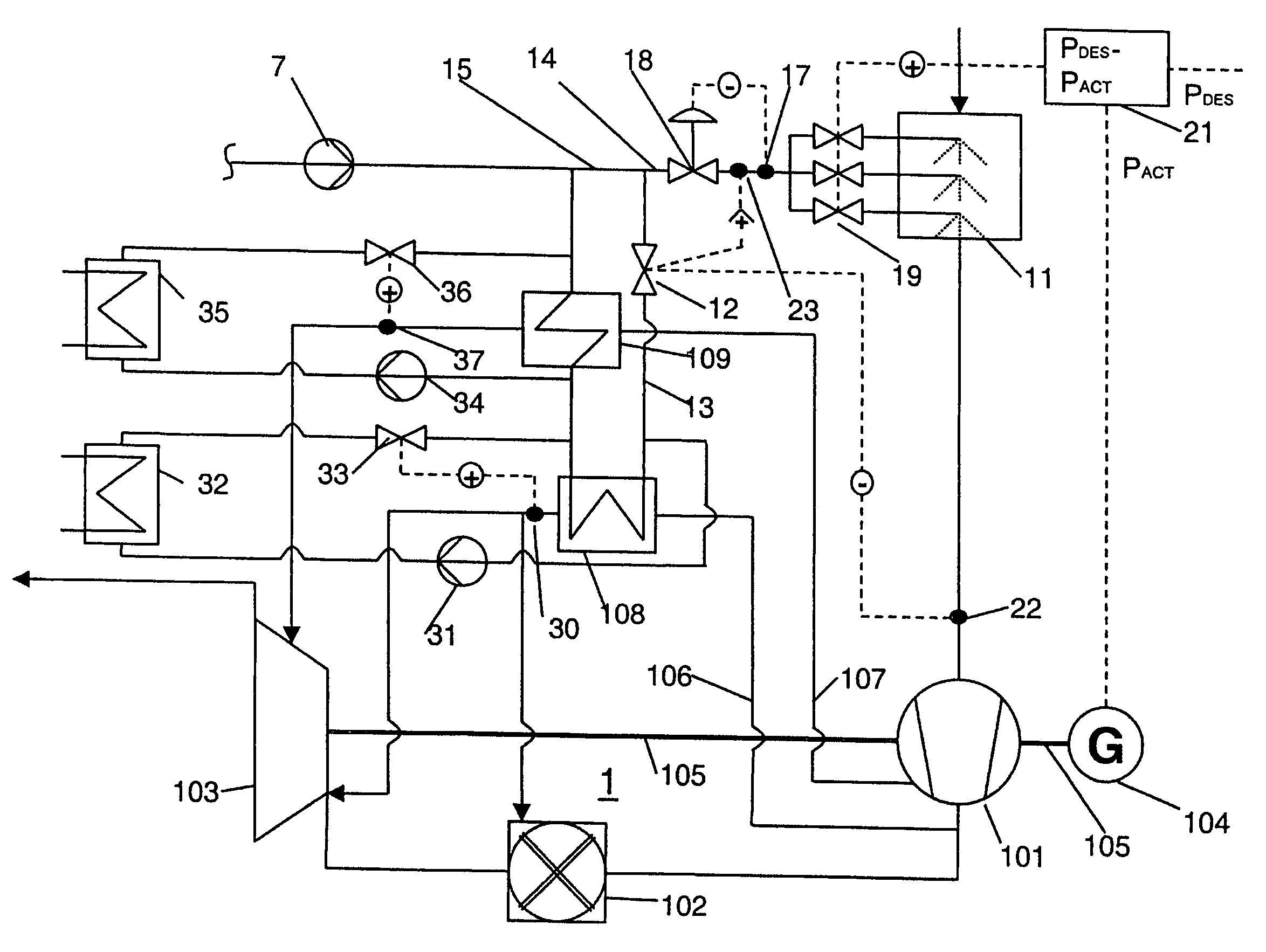
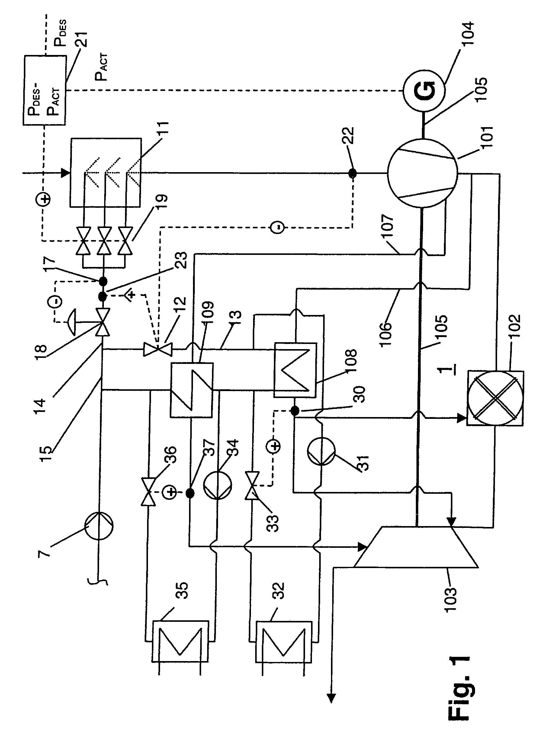
[0035]FIG. 1 illustrates a gas turboset which, in a manner which is known per se, comprises a compressor 101, a combustion chamber 102, a turbine 103 and a generator 104. The turbine drives the compressor and the generator via a shaft 105. The gas turboset illustrated also has an injection and atomization device 11 for a liquid, in particular water, arranged upstream of the compressor inlet. Liquid which is injected there can increase the power and efficiency of the gas turboset in two ways: firstly, some of the liquid injected as a mist of droplets is evaporated while it is still in the intake duct, with the result that the compressor intake air is cooled, bringing about an increase in the density of the intake air and in the mass flow which is delivered. Furthermore, liquid drops which penetrate into the compressor effect intensive internal cooling in the compressor, which consequently takes up less power, with the result that more of the turbine power is available for driving the...


PUM


Abstract

A power plant comprises an air-breathing combustion engine having an air inlet and an inflow duct arranged upstream of the air inlet, as well as an atomization device arranged in the inflow duct. In a method for operating this power plant, a liquid is injected into the inflow duct in the atomization device. During the injection, at least the temperature of the atomization liquid which is to be injected upstream of the atomization device or the temperature in the inflow duct downstream of the atomization device is measured. One of these measured temperatures is used as control variable for control of the temperature of the atomization liquid.

Description

RELATED APPLICATIONS[0001]This application claims priorities under 35 U.S.C. § 119 to Swiss Application No. 1856 / 03 , filed Oct 30, 2003 , and as a Continuation Application Under 35 U.S.C. § 120 to PCT Application No. PCT / EP 2004 / 052681 filed as an International Application on Oct 28, 2004 designating the U.S., the entire contents of which are hereby incorporated by reference in their entireties.FIELD OF THE INVENTION[0002]The present invention relates to a method for operating a power plant in accordance with the preamble of claim 1, and to a power plant which is particularly suitable for carrying out the method.BACKGROUND OF THE INVENTION[0003]In the prior art, for example from DE 25 49 790, it is well known to inject a liquid into the intake section of combustion engines, such as for example gas turbosets. The evaporation of the liquid cools the intake air and increases power. The effect can be boosted further if the injected liquid mass flow is selected to be so great that the i...

Claims


Application Information

Patent Timeline
Patent Type & Authority Patents(United States)
IPC IPC(8): F02C3/30F02C7/143
CPCF02C7/143F02C7/1435Y02E20/16
Inventor HAERTEL, CARLOS JIMENEZSAVIC, SASHADITTMANN, ROLF
Owner ANSALDO ENERGIA IP UK LTD
Why Eureka
Try Eureka