Supercharge Your Innovation With Domain-Expert AI Agents!

Variable valve timing control apparatus of internal combustion engine

a timing control and internal combustion engine technology, applied in the direction of valve arrangement, yielding coupling, coupling, etc., can solve the problems of deterioration of engine startability or instability of idling, braking torque occurrence at engine start-up, and relatively large sleeve and timing sprock

Inactive Publication Date: 2009-01-27
HITACHI LTD
View PDF2 Cites 6 Cited by
  • Summary
  • Abstract
  • Description
  • Claims
  • Application Information

AI Technical Summary

Benefits of technology

Stabilizes engine start-up and prevents deterioration of exhaust emission performance by ensuring proper rotational phase alignment, even in cold conditions, and adjusts phase alignment according to engine operating conditions.

Problems solved by technology

In particular, high viscosity of the lubricating oil residing in spaces or gaps between the pole teeth causes an occurrence of braking torque at the engine start-up.
Further, this turns the timing sprocket and the sleeve relatively, and there is a case where an improper action such as a shift of the rotational phase of the camshaft to an advanced phase will occur.
In this case, there are risks that, for instance, not only deterioration of engine startability or instability of idling but also deterioration of exhaust emission performance will occur.

Method used


Image

  • Variable valve timing control apparatus of internal combustion engine
  • Variable valve timing control apparatus of internal combustion engine
  • Variable valve timing control apparatus of internal combustion engine

Examples


second embodiment

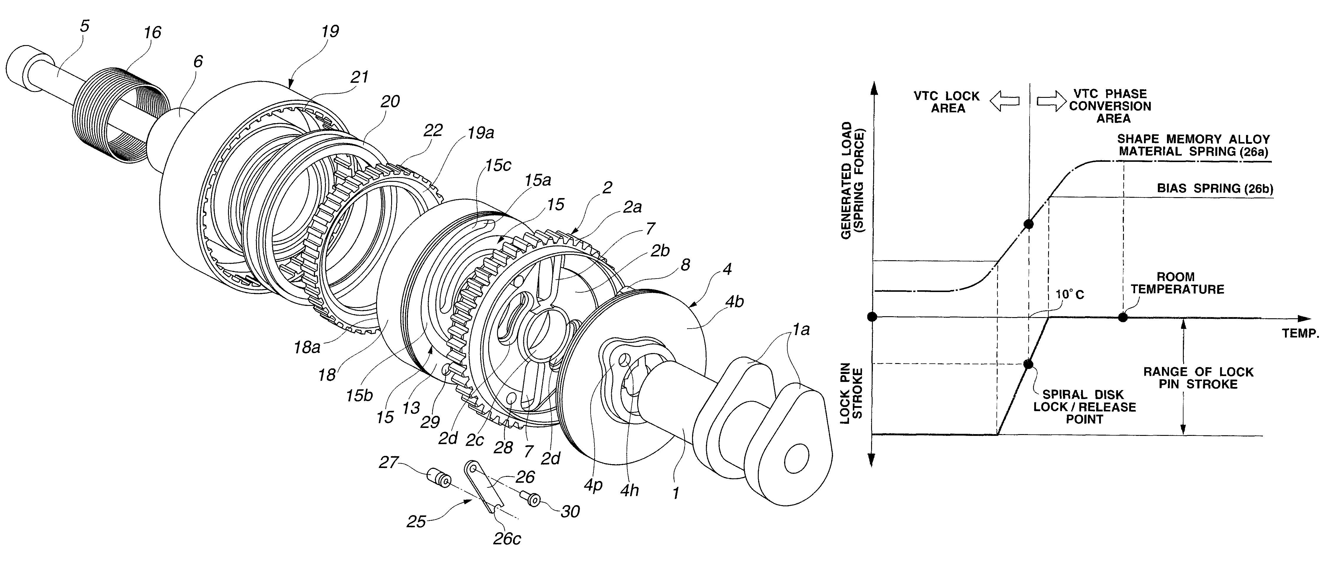
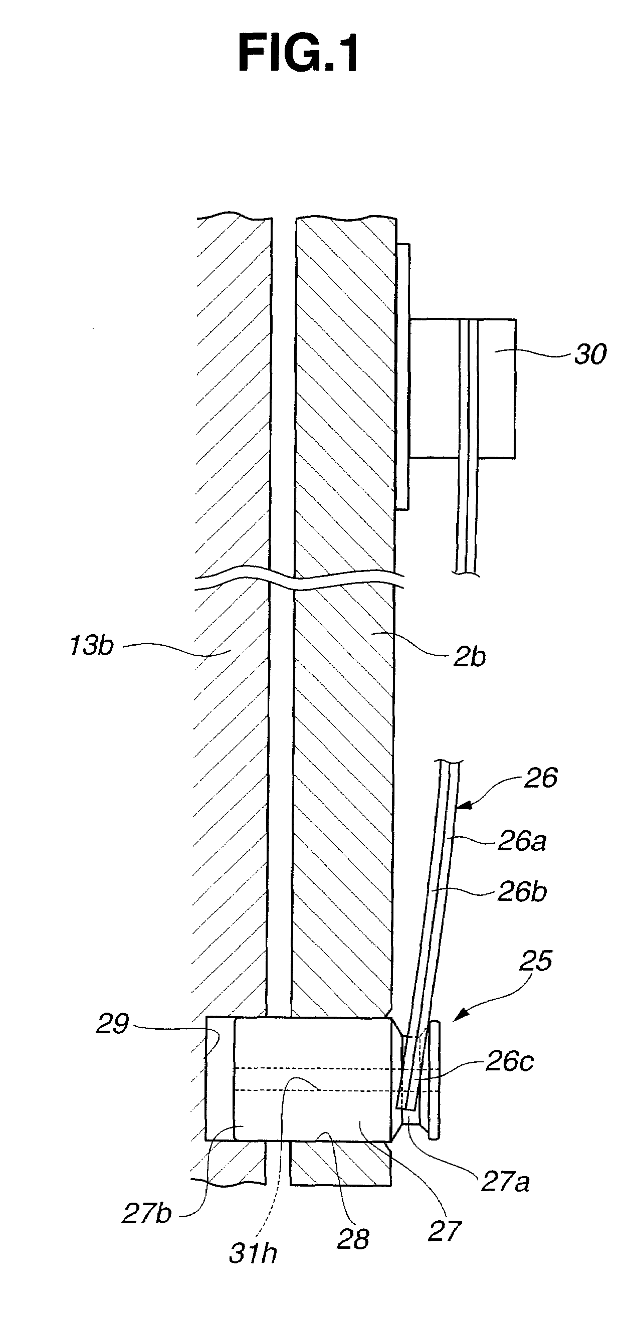
[0073]FIG. 9 illustrates characteristics of an amount of bending deformation and an oil temperature of a case where the configuration or structure of the bimetal 26 is changed, as the present invention. In this embodiment, the bimetal 26 is formed by coupling or bonding two metal sheets or plates; a shape memory alloy spring 26a at the side of the spiral guide disk 13 and a bias spring 26b that keeps rectilinearity.

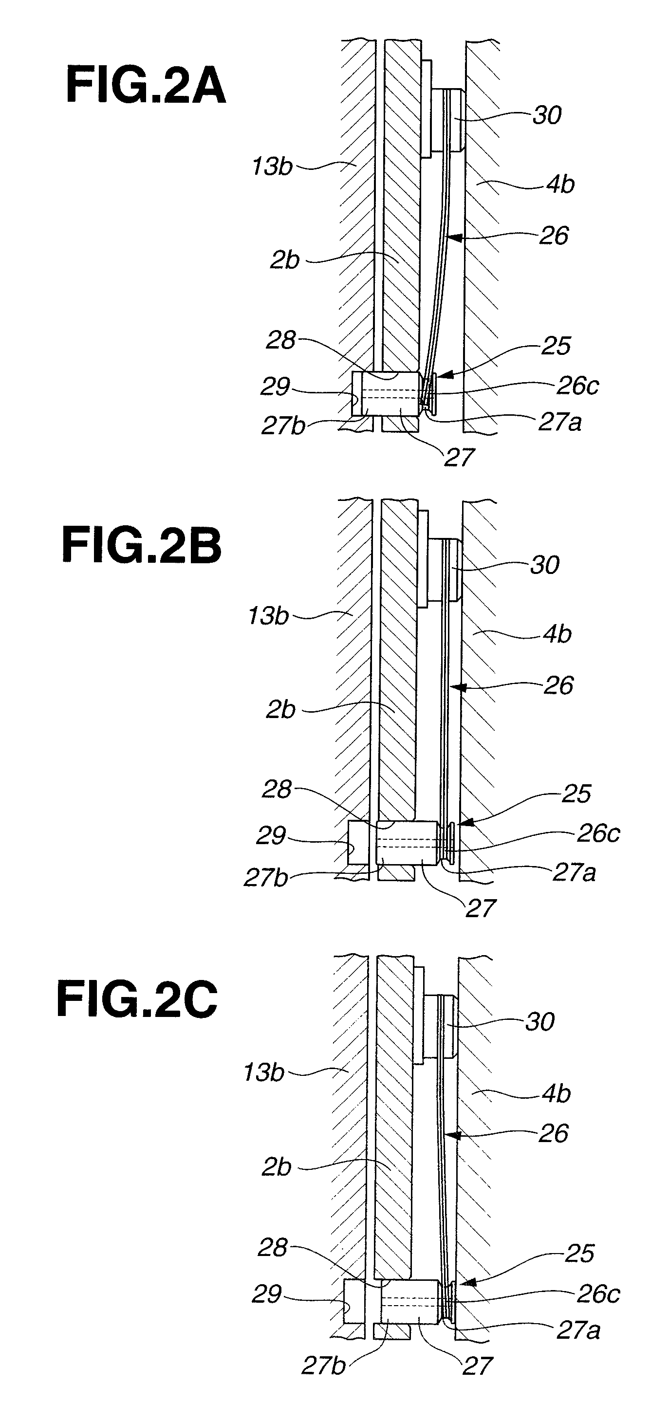
[0074]As can be seen in FIG. 9, the shape memory alloy spring 26a is curvedly deformed (bends down) with the oil temperature of almost 10° C. being a border. When the oil temperature becomes substantially lower than or equal to 10° C., the shape memory alloy spring 26a is deformed by a balance of spring forces (loads) between the shape memory alloy spring 26a and the bias spring 26b, and the lock pin 27 is inserted into the connecting hole 29.

[0075]More specifically, for example, when the oil temperature is room temperature such as about 20° C., the spring force (the spri...

first embodiment

[0083]Concerning the position where the connecting hole 32 is formed at the large-diameter stepped flange portion 4b, in the same manner as the first embodiment, it is set such that both positions of the connecting hole 32 and the other end portion 31b are fitted with each other (namely that the other end portion 31b can be inserted into the connecting hole 32) under the condition where the engaging pin 11 is positioned at the top end portion of the outermost groove section 15a of the spiral guide groove 15 (i.e. under the condition of the slightly advanced phase position from the most-retarded phase position).

[0084]The configuration or formation of the bimetal 26 is similar to the first embodiment. However, in this embodiment, the bimetal 26 is set such that when the oil temperature becomes substantially lower than or equal to 10° C., the bimetal 26 bends down or curves in a direction of the large-diameter stepped flange portion 4b, and also when the oil temperature becomes substan...


PUM


Abstract

A variable valve timing control apparatus of an internal combustion engine, has a drive rotary member rotated by an engine crankshaft; a driven rotary member fixed to a camshaft that has a cam opening / closing an engine valve, the driven rotary member driven by the drive rotary member; a phase-change mechanism provided between the drive and driven rotary members and changing a relative rotational phase between the drive and driven rotary members; and a locking mechanism. The locking mechanism links any two of the drive rotary member, the driven rotary member and the phase-change mechanism or releases the link in accordance with temperature of the phase-change mechanism.

Description

BACKGROUND OF THE INVENTION[0001]The present invention relates to a variable valve timing control apparatus of an internal combustion engine, which variably controls open and closing timing of an intake valve and / or an exhaust valve of the engine via electromagnetic force.[0002]In recent years, there have been proposed and developed various electromagnetic force type variable valve timing control apparatuses. One such variable valve timing control apparatus has been disclosed in Japanese Patent Provisional Publication No. 2004-239231 (hereinafter is referred to as “JP2004-239231”).[0003]The variable valve timing control apparatus disclosed in JP2004-239231 includes a timing sprocket to which a torque (turning force) is transferred from a crankshaft of an engine, a camshaft relatively rotatably supported within a predetermined angular range with respect to the timing sprocket, a sleeve fixedly connected to the camshaft, and a rotational phase control mechanism (or a relative angular ...

Claims


Application Information

Patent Timeline
Patent Type & Authority Patents(United States)
IPC IPC(8): F01L1/34
CPCF01L1/022F01L1/344F01L1/024F01L2001/34469F01L2001/34483F01L2820/031F01L2820/032
Inventor WATANABE, MASAHIKOYAMANAKA, ATSUSHI
Owner HITACHI LTD
Features
  • R&D
  • Intellectual Property
  • Life Sciences
  • Materials
  • Tech Scout
  • Unparalleled Data Quality
  • Higher Quality Content
  • 60% Fewer Hallucinations
Learn More