
Structure for preventing shaft of constant velocity joint from coming off

a constant velocity joint and structure technology, applied in the direction of manufacturing tools, furniture parts, couplings, etc., can solve the problem that the shaft cannot be pulled out, and achieve the effect of preventing the disassembly of the inner joint member and the shaft, preventing disassembly, and allowing disassembly

Inactive Publication Date: 2009-01-27
NTN CORP
View PDF10 Cites 13 Cited by
  • Summary
  • Abstract
  • Description
  • Claims
  • Application Information

AI Technical Summary

Benefits of technology

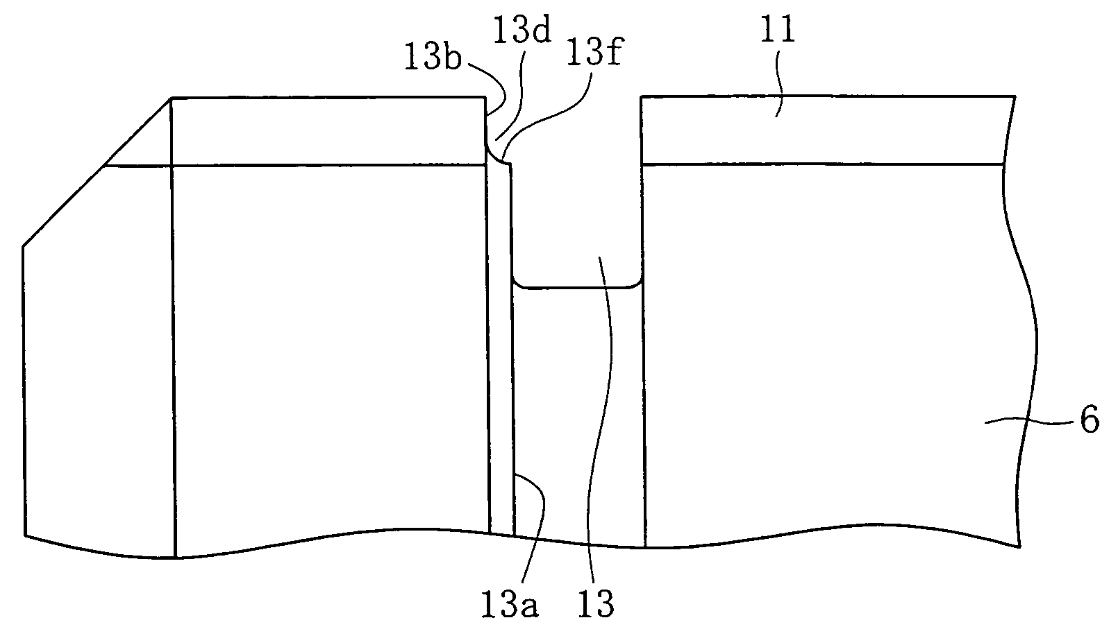
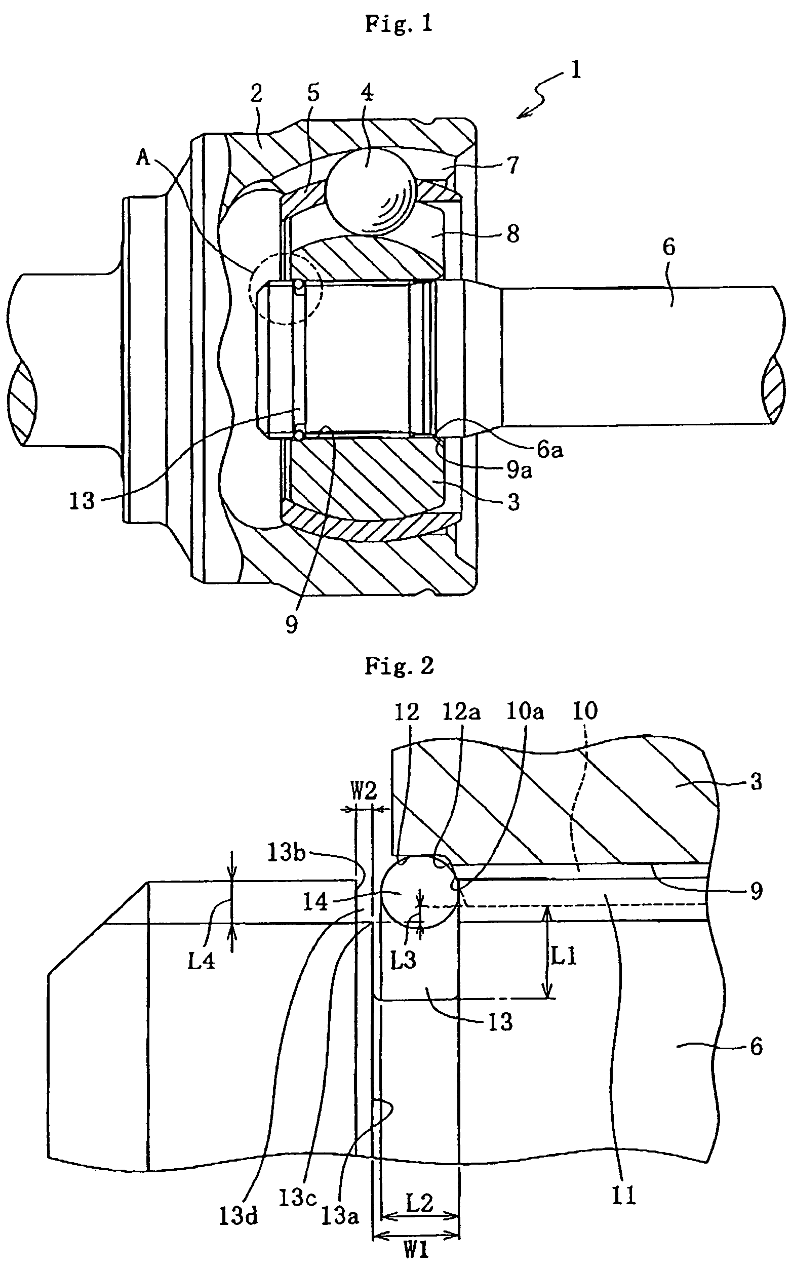
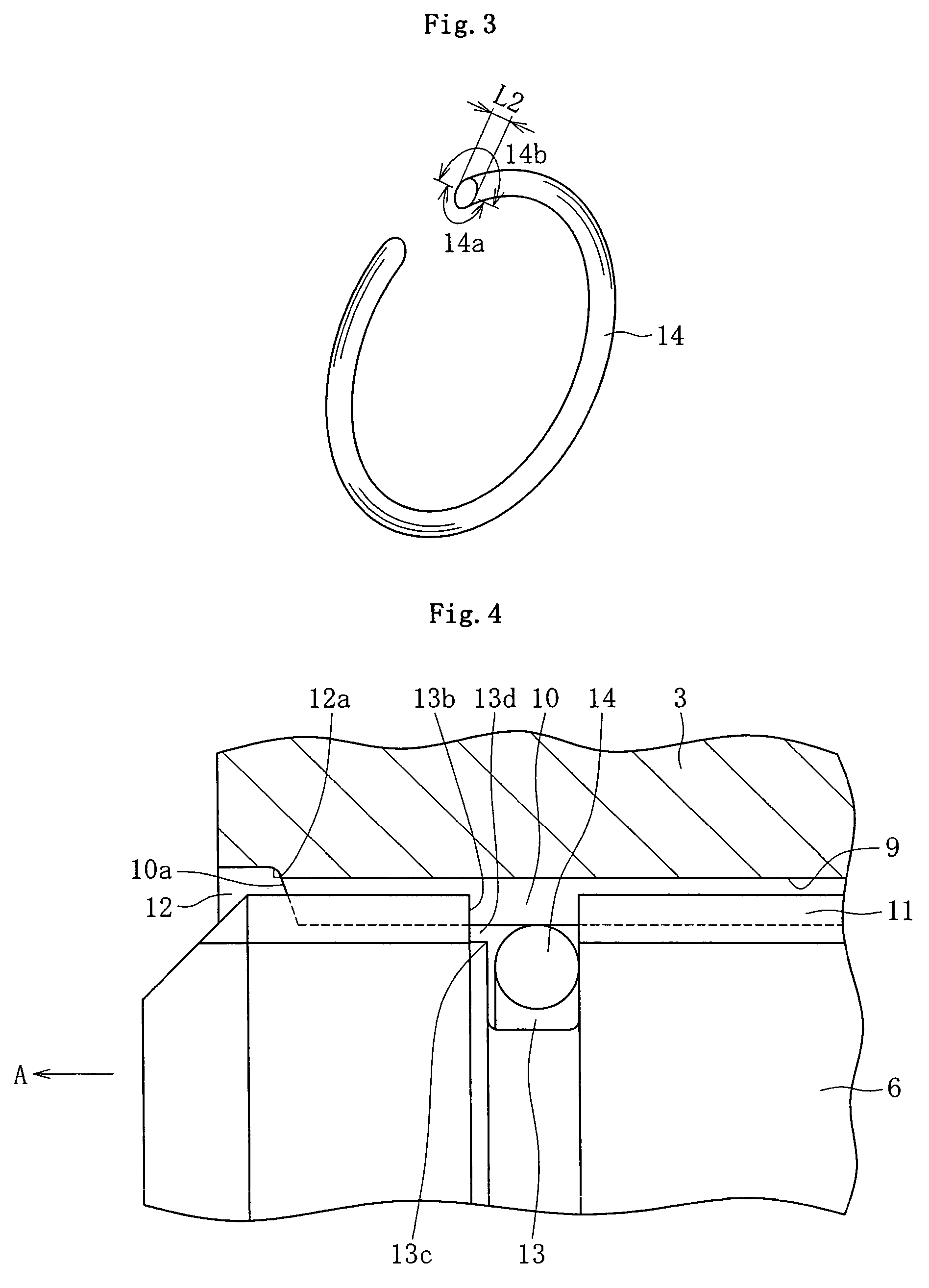
The present invention provides a structure for preventing a shaft from coming off a constant velocity joint. The structure includes an inner joint member, a shaft, and a retaining ring. The retaining ring is elastically expandable and contractable and is located between a slope part of the inner joint member and a ring-shaped retaining ring groove in the shaft. The retaining ring is prevented from contracting when a pulling force is applied to the shaft because of contacting points on the inner surface of the retaining ring. The structure also includes a step part on one side of the retaining ring groove that has a depth less than the thickness of the retaining ring. The shaft and inner joint member are coupled through a spline section, and the retaining ring is sandwiched between the contacting points of the groove and the slope part of the insertion hole, preventing inward movement of the ring. The structure prevents disassembly of the inner joint member and the shaft without the need for a particular inner joint member and a particular retaining ring, reducing parts control requirements.

Problems solved by technology

Thus, the shaft cannot be pulled out.

Method used


Image

  • Structure for preventing shaft of constant velocity joint from coming off
  • Structure for preventing shaft of constant velocity joint from coming off
  • Structure for preventing shaft of constant velocity joint from coming off

Examples


Embodiment Construction

[0025]Referring now to FIG. 1 to FIG. 8, the embodiments of the present invention will be explained. For convenience of explanation, “front edge side” denotes the left side in the drawings and “anti-front edge side” denotes the right side in the drawings. For convenience, explanations will be given referring to a fixed type constant velocity joint, as shown in FIG. 1, in which the inner joint member is also referred to as an inner ring.

[0026]As shown in FIG. 1, the fixed type constant velocity joint 1 comprises outer ring 2, inner joint member 3, torque transmission ball 4, and cage 5 for torque transmission ball 4. Further, shaft 6 for transmitting torque is mounted to the inner joint member 3 in an engaging manner. The constant velocity joint is not limited to the fixed type constant velocity joint 1, and may be a sliding movement type constant velocity joint such as a double-offset type, a cross-groove type, a tripod type, or the like. The inner joint member in the double-offset ...


PUM


Abstract

A constant velocity joint structure including an inner joint member, a retaining ring, and a shaft which are configured to prevent the shaft from being withdrawn from the inner joint member when a pulling force is applied to one side of the shaft is disclosed. A retaining ring groove is disposed at an opposite side of the shaft. In a preferred embodiment, the retaining groove has at least two points which contact an inner surface of the retaining ring when the pulling force is applied to prevent the retaining ring from contracting in a radial direction, thereby preventing the shaft from being withdrawn from the inner joint member.

Description

BACKGROUND OF THE INVENTION[0001]1. Field of the Invention[0002]The present invention relates to a spline engagement structure for coupling an inner joint member with a shaft of constant velocity joints used in automobiles and various industrial equipment.[0003]2. Description of the Related Art[0004]In conventional constant velocity joints for a driving system or the like of automobiles, an inner joint member and a shaft are engaged detachably, and a structure for preventing the shaft from coming off is employed for reduction of the maintenance man-hours for replacement of boots or the like. In this structure, a groove is formed at an end face of the shaft, a retaining ring is provided in this groove, and the shaft is engaged with a contacting face being formed on the inner joint member by means of elastic expansion of the retaining ring. A corner is provided on the contacting face to interfere with the retaining ring when the shaft is pulled out, and disengagement is performed by r...

Claims


Application Information

Patent Timeline
Patent Type & Authority Patents(United States)
IPC IPC(8): F16D1/116
CPCF16D3/223F16D2003/22313Y10T403/7033Y10S464/906Y10S403/07F16D2300/12F16D2001/103F16D1/116
Inventor FUKUMURA, YOSHIKAZUUENO, TSUYOSHISHINBA, CHIKAYASHIBATA, TAKAAKI
Owner NTN CORP
Learn More