
Apparatus for aspirating liquids from sealed containers

a technology of aspirating liquid and sealed containers, which is applied in the field of aspirating liquid apparatus improvement, can solve the problems of affecting the operation of the apparatus, adding considerable weight to the instrument, and affecting the quality of the liquid, so as to reduce the number of components and reduce the cost

Active Publication Date: 2009-01-27
BECKMAN COULTER INC
View PDF29 Cites 10 Cited by
  • Summary
  • Abstract
  • Description
  • Claims
  • Application Information

AI Technical Summary

Benefits of technology

The invention is an improved apparatus for aspirating liquid from a sealed container, such as a test tube. Compared to prior art instruments, the apparatus is simpler and lighter in weight, requiring no heavy stabilization equipment. It includes a support frame, a drive motor, a tube detector / stripper member, a second drive motor, and an aspiration probe. The drive motor selectively and incrementally moves the aspiration probe towards the puncturable stopper on the tube, while the tube detector / stripper member engages the top of the stopper and holds the probe in place. The invention reduces the number of components, simplifies construction, and lowers costs.

Problems solved by technology

Thus, it will be appreciated that this approach is disadvantageous if only from the standpoint that it adds considerable weight to the instrument.
While the aspirating apparatus of McCandless et al. does, indeed, facilitate the stripping function, it does so at the cost of a relatively complex mechanism.
Further, the apparatus may be viewed as problematic in that it requires repositioning of the entire liquid aspiration apparatus after cap-piercing has been effected to align the aspiration probe with the container axis, and it further requires substantially perfect parallel alignment between two independently movable shafts, i.e., the aspiration probe and the cap-piercing member.
The latter can be particularly problematic since any binding friction caused by the misalignment between the two shafts can produce a malfunction of the apparatus.

Method used


Image

  • Apparatus for aspirating liquids from sealed containers
  • Apparatus for aspirating liquids from sealed containers
  • Apparatus for aspirating liquids from sealed containers

Examples


Embodiment Construction

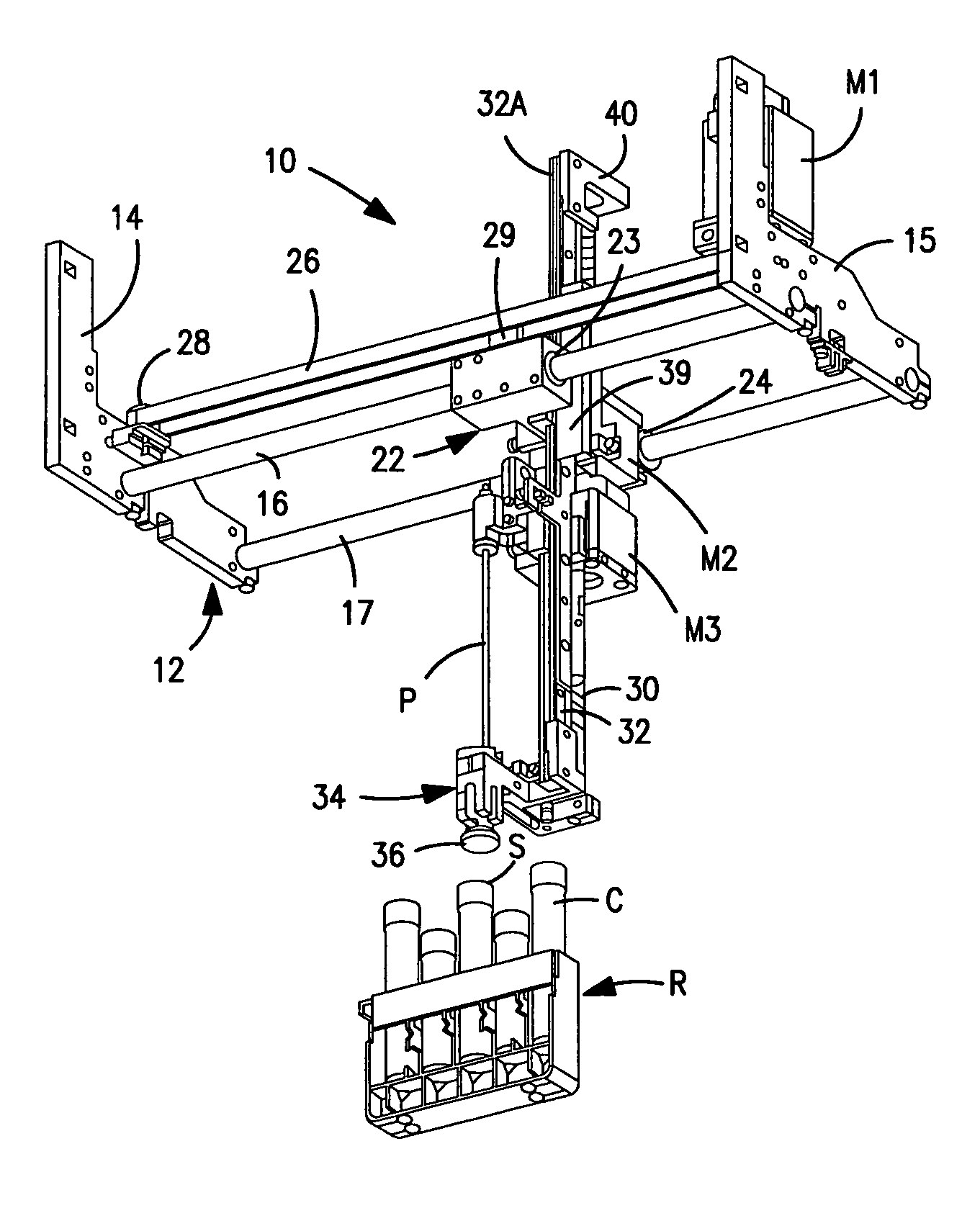
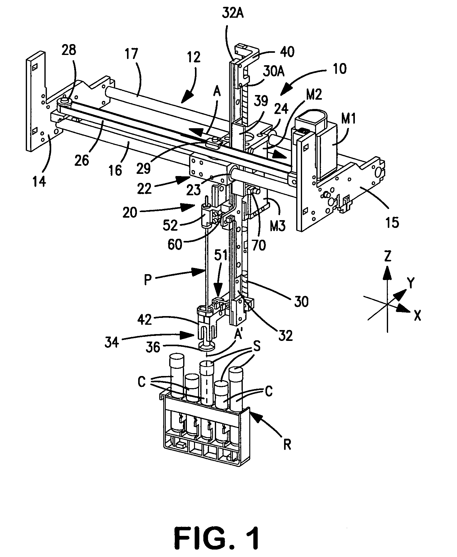
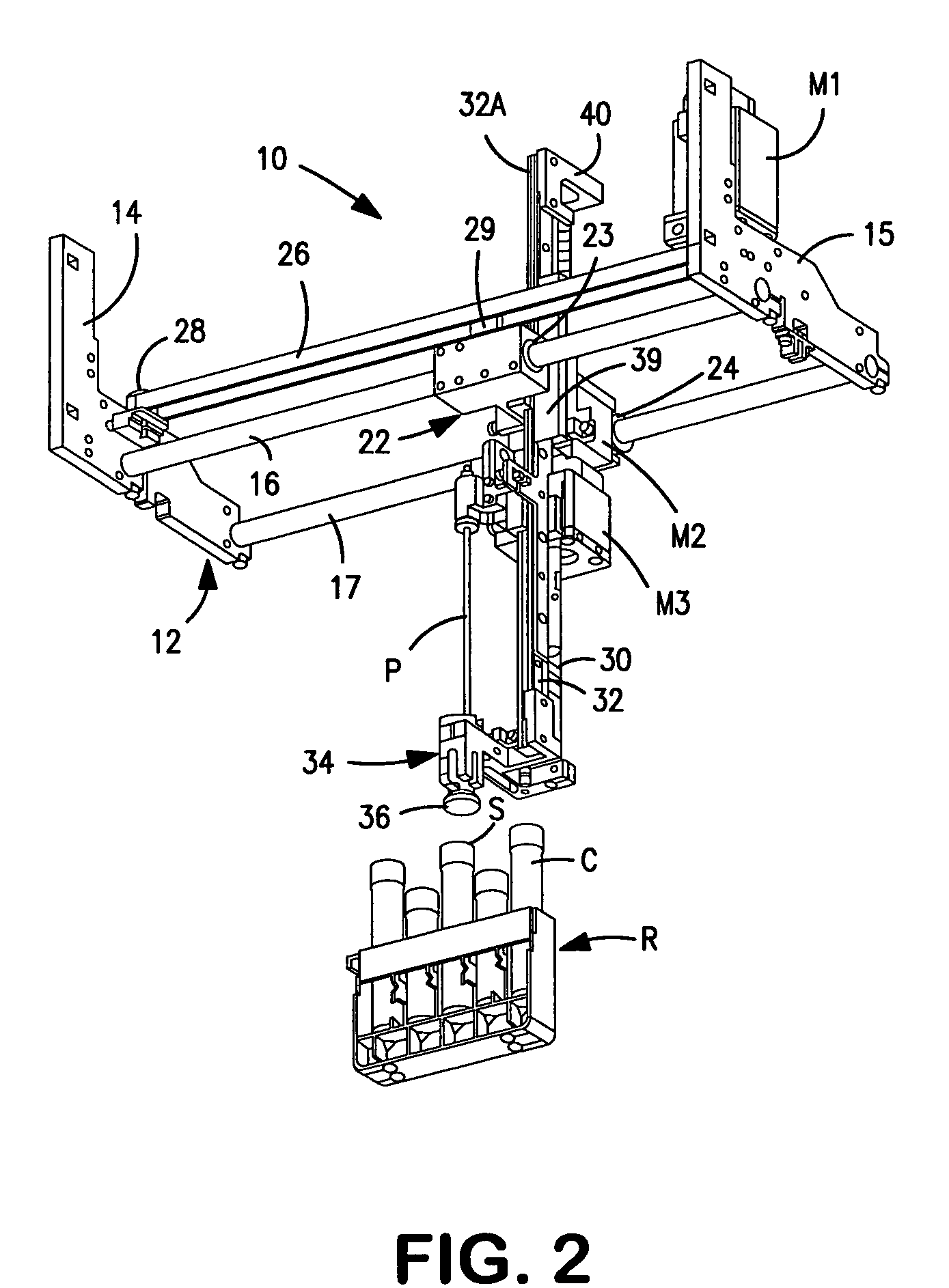
[0019]Referring now to the drawings, FIGS. 1-4 illustrate a preferred apparatus 10 for selectively aspirating liquid contained in each of a plurality of sealed containers C supported in an upright orientation by a rack R. As illustrated, each container may be in the form of a conventional test tube or the like having a puncturable stopper S, e.g., made of a suitable rubber or synthetic rubber, that acts to seal the normally open end of the tube. While the tubes may vary in size considerably, as illustrated, the tube-support rack operates to arrange their respective longitudinal axes at equal distances and in a common vertical plane. From the description below, it will be appreciated that the liquid aspirating apparatus of the invention is capable of aspirating liquid from any of the various tube sizes that the rack can accommodate. Further, it will be understood that, during use of the liquid aspirating apparatus, the tube rack remains stationary while the liquid aspiration apparatu...


PUM

PropertyMeasurementUnit
weightaaaaaaaaaa
volumeaaaaaaaaaa
electrical currentaaaaaaaaaa

Abstract

Apparatus for aspirating liquid from a container, e.g., a test tube, having a puncturable stopper includes a pair of stepper motors that share a common linear actuator or drive member. One motor operates to axially advance the linear drive member (preferably a lead screw) to a position in which it serves to position a rigidly connected tube-detector / stripper member in engagement with the top of a stopper on a tube. Thereafter, the second motor operates to move along the surface of the same drive member to advance an aspiration probe through the engaged stopper and into a liquid aspirating position within the tube. Preferably, a linear guide rail, slidably-mounted on a frame that supports the liquid-aspirating apparatus, serves to guide both the movement of the aspiration probe and the linear drive member. As a result of the shared components, the apparatus is highly precise and reliable.

Description

BACKGROUND OF THE INVENTION[0001]1. Field of the Invention[0002]The present invention relates to improvements in apparatus for aspirating liquids, such as biological specimens, from containers for processing. The invention is particularly useful in automated hematology instruments for extracting blood samples from sealed test tubes and the like for analysis.[0003]2. The Prior Art[0004]In conducting tests on biological liquids, it is common to employ automated instruments to extract liquid specimens from sealed containers, e.g., test tubes and the like. Such instruments typically include a movably-mounted sample aspiration probe that is adapted to puncture a rubber stopper atop a stationary specimen container to access and aspirate the liquid therein. These instruments often include a mechanism for sensing the presence of a specimen container at a desired specimen-aspiration position before the probe is moved in a direction to expose the probe tip, and most instruments include a devi...

Claims


Application Information

Patent Timeline
Patent Type & Authority Patents(United States)
IPC IPC(8): B01L3/02G01N1/00
CPCG01N35/1079B01L3/0293G01N2035/0405B01L9/52B01L13/02
Inventor LI, WILLIAM WEIGONGVEINER, CRAIG R.CABRERA, SERGIO
Owner BECKMAN COULTER INC
Learn More