Stent delivery and deployment system

a technology of stenose and stenose, which is applied in the field of angioplasty, can solve the problems of cumbersome and undesirable requirements, too long stenose, and insufficient stenose length,

Active Publication Date: 2009-02-03
CIAMACCO JR SAM
View PDF53 Cites 18 Cited by
  • Summary
  • Abstract
  • Description
  • Claims
  • Application Information

AI Technical Summary

Benefits of technology

[0021]This invention relates to the insertion, delivery and deployment of one or more stents into the arterial or venal system of the human body. In particular, this invention relates to the incorporation of a unique guide wire passage into the structure of the conventional stent whereby the guide wire can be inserted and the stent slidably engaged on the guide wire becomes the guide means to transport one or more balloon angioplasty catheters into the area of the stenosis. Using the stent slidably engaged on the guide wire also eliminates the need for a guide wire lumen.
[0023]The principle of this invention is that there is a separate tubular guide wire passageway formed on the stent substantially parallel to the tubular stent central cavity incorporated into the design structure of the stent. This passageway provides for engagement of the stent with the pre-positioned guide wire. With the stent engaged with a catheter or other means to translate it along the guide wire, the stent becomes a means to track and guide the inserted device attached to it, such as a balloon catheter, and eliminates the need for the guiding catheter and other parts conventionally used. A preferred embodiment of the invention will have the guide wire passage in a coaxial position when the balloon angioplasty catheter and stent are in a compressed state. When the stent is in the expanded condition, the guide wire passage can be located either completely out of the stent central cavity, half in and half out of the stent central cavity, or completely within the central cavity of the stent and still be covered within the scope of this patent. Or, as those skilled in the art will see, the guide wire passage may be located any percentage in and out of the central cavity as the design and use permits and dictates and such is anticipated.
[0024]A secondary feature of this invention is the unique capability of the distal end of the stent being able to overlap or interlock with the proximal end of a previously implanted stent without removal of the guide wire. Overlapping of two or more stents is accomplished by the means of relieving the inner surface of material on the distal ends, and relieving the outer surface of material on the proximal ends of the stents. The means of interlocking of the stents is accomplished by under cutting the inner surface at the adjoining end of one stents, and under cutting the outer surface on the adjacent end of the adjacently placed stents. Additionally, the guide wire passage can be stepped in on the distal end of the stent and stepped out on the proximal end of the stent, adding to the exact alignment and nesting of one stent into another.
[0030]A further object of this stent delivery and deployment system is to provide the ability for overlapping, interlocking, or other means to cooperatively engage two adjacent stents together.
[0032]Another object of this invention is to provide a system for physicians and surgeons to be able to treat a stenosis that exceeds the length of conventional existing stents without having a gap between multiple stents and having those stents form an integral structure.

Problems solved by technology

Because such conventional stent delivery catheters have a guide wire lumen which extends the entire length of the catheter, they cannot be inserted to the stenosis site over the guide wire that is used to insert the balloon angioplasty catheter (such guide wires are too short).
In situations where physicians find it desirable to install a stent after the balloon angioplasty procedure, the need to replace the guide wire with an exchange guide wire is a cumbersome and undesirable requirement.
Additionally, physicians find that some stenoses are too long for a single stent insertion and more than one stent is required to complete the procedure, requiring a gap between each stent.
This gap has been found to be undesirable and a possible location where an additional stenosis may develop.
Early application of a stent after the occurrence of occlusion and / or dissection decreases the need for emergency bypass surgery and the risk for myocardial infarction (MI).
Although the '642 patent eliminates the need for the exchange-length guide wire, it provides no means to engage a second stent without removing the angioplasty catheter guide wire and restarting the procedure.

Method used


Image

  • Stent delivery and deployment system
  • Stent delivery and deployment system
  • Stent delivery and deployment system

Examples


Embodiment Construction

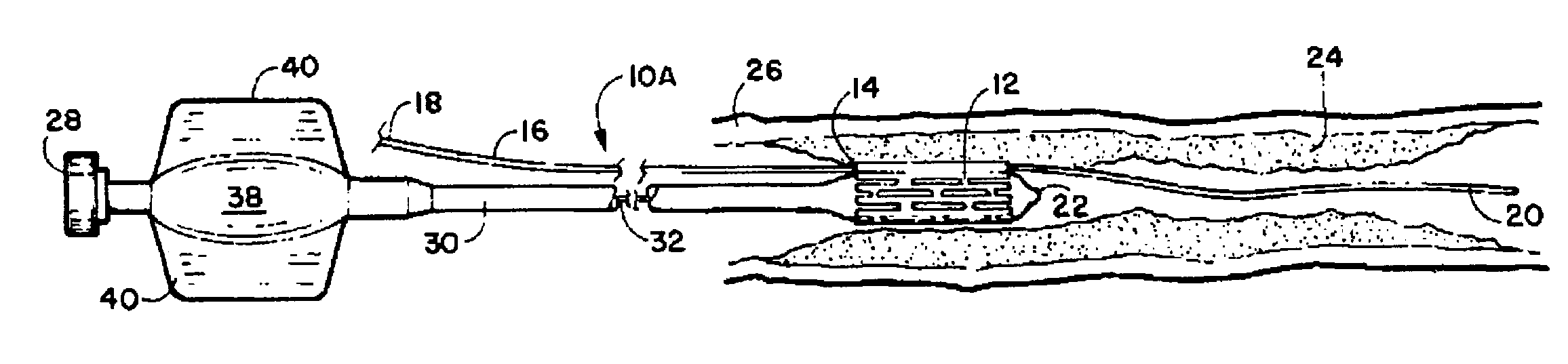
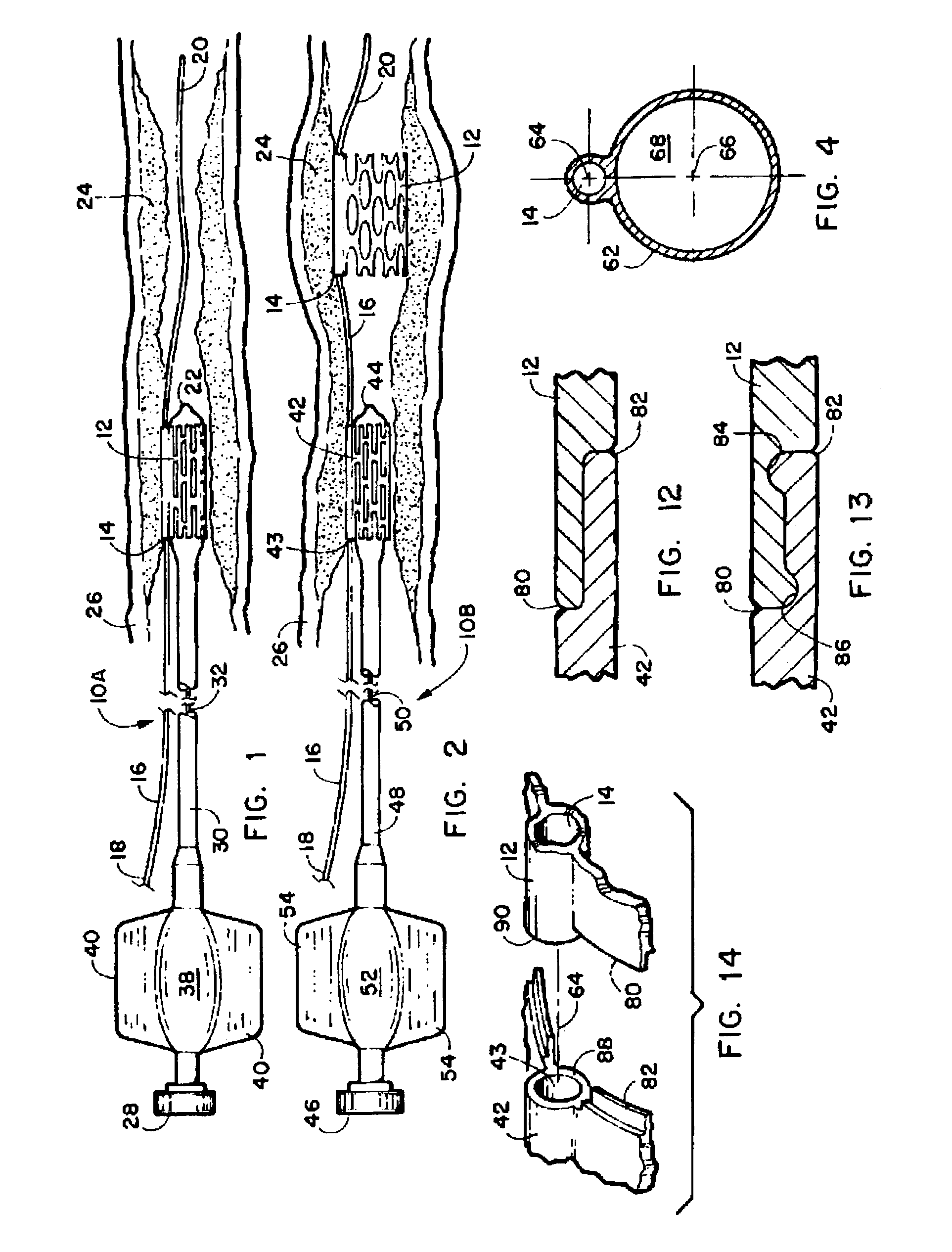
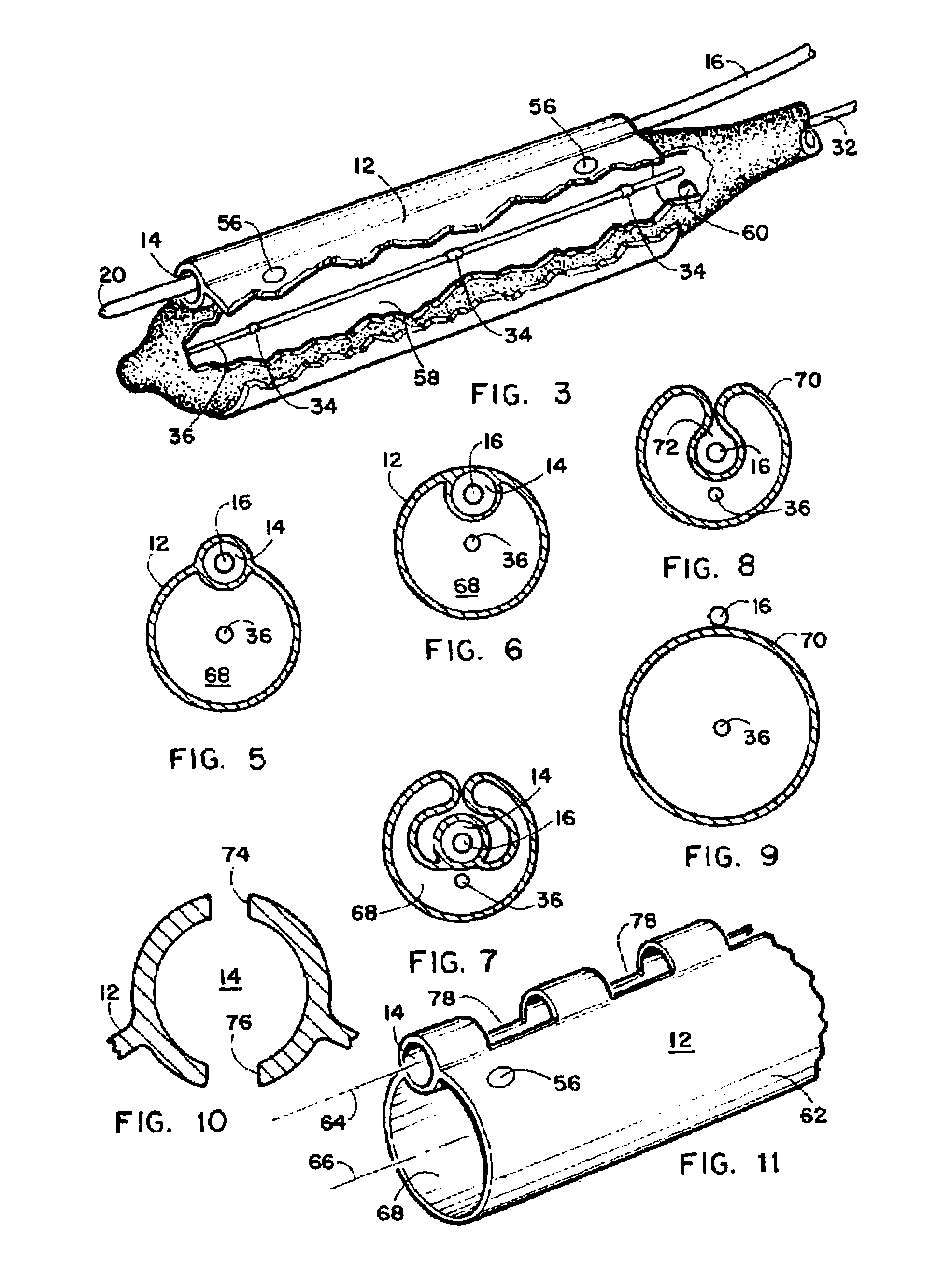
[0049]Referring now to the drawings FIGS. 1-14, wherein similar parts of the invention are identified by like reference numerals, there is seen in FIG. 1 a first preferred embodiment of the stent delivery and deployment system 10A. The device depicted consists of a stent 12 with the guide wire passage 14 formed integral to or upon a wall surface of the stent 12. The guide wire passage 14 engages and translates the stent 12 over the guide wire 16 extending from outside the patients' body at the guide wire's proximal end 18, through the arterial or venal system of the patient, to the guide wire distal end 20. The stent 12 is shown operatively engaged on the balloon angioplasty catheter 22 within an elongated arterial stenosis 24 within a typical blood vessel 26 such as a coronary artery, vein, or neurovascular blood vessel of a patient. The balloon angioplasty catheter 22 as shown provides a means to laterally translate stent with the guide wire 16 engaged through the guide wire passa...


PUM


Abstract

A stent delivery and deployment system for placement of vascular stents. The device employs a guide wire which is threaded into position in a vein or artery of a patient. An elongated stent having a central cavity communicating therethrough also has a passageway formed axially on or integral to, the sidewall defining the central cavity. The passageway has a diameter sufficient in size to slide upon the guide wire to allow the stent to be translated to the desired position in the blood vessel with the guide wire engaged in the passage. Sliding the stent to the proper position is accomplished by insertion of a balloon angioplasty catheter engaged with the stent, or other means to translate the stent on the guide wire, and sliding the stent with the on the engaged guide wire to the desired position. Once so positioned the stent is expanded and engaged in the blood vessel and the catheter may be removed leaving the guide wire in place for subsequent placement of additional stents or removal. The device also provides for positioning of stents adjacent to each other without gaps therebetween and cooperatively engaging adjacent stents if desired.

Description

FIELD OF THE INVENTION[0001]The present invention relates to the field of angioplasty. More particularly, the disclosed device provides for the insertion, delivery and deployment of one or a plurality of stents into the arterial or venal system of the human body which also has unique abutment, overlapping and interlocking capabilities provided by guiding the stent to position using a single in-place guide wire. Additionally, the device provides for the addition of one or more stents with or without overlapping or interlocking capabilities adjacent to an existing implanted stent within the arterial or venal system of the human body.BACKGROUND OF THE INVENTION[0002]The use of balloon angioplasty catheters to treat strictures, stenoses, or narrowing of the arterial or venal system within various parts of the human body is well known. In a typical procedure, for example, to dilate a blockage or stenosis in the coronary or other arteries in the body, conventionally a relatively large gui...

Claims


Application Information

Patent Timeline
Patent Type & Authority Patents(United States)
IPC IPC(8): A61F2/06A61F2/82
CPCA61F2/82A61F2/95A61F2/958A61F2/844A61F2002/826A61M2025/0183
Inventor CIAMACCO, JR., SAM
Owner CIAMACCO JR SAM
Why Eureka
Try Eureka