Water treatment method and water treatment apparatus

a water treatment method and water treatment technology, applied in multi-stage water/sewage treatment, filtration separation, separation process, etc., can solve the problems of less easily microbially decomposable, less organic fluoric compounds, and incurring a fear of bad influences on ecosystems

Inactive Publication Date: 2009-02-03
SHARP KK
View PDF30 Cites 9 Cited by
  • Summary
  • Abstract
  • Description
  • Claims
  • Application Information

AI Technical Summary

Benefits of technology

[0019]In this invention, microorganisms propagated on the charcoal are activated by micro-nano bubbles contained in the treatment water. Since the water treatment is carried out with those activated microorganisms propagated on the charcoal, a stable treatment is achieved and moreover organic matters adsorbed by the charcoal is decomposed by the activated microorganisms propagated on the charcoal. The decomposition of organic matters by the microorganisms goes as if charcoal were automatically regenerated. Thus, according to this invention, it is no longer necessary to do charcoal replacement work, so that the running cost can be reduced. As a consequence, according to the invention, the water treatment method is capable of microbially decomposing organofluoric compounds with high efficiency.
[0042]In this embodiment, when a large amount of microorganisms have occurred in the water treatment water tank, microorganisms adhere to the upper polyvinylidene chloride filler material. Therefore, the granular activated carbon in the intermediate section and the wood charcoal in the lower section are prevented from being blocked by microorganisms, which allows the water treatment to be continued. In the case where the treatment water is reuse water in a semiconductor factory as an example, solvents may mix into the treatment water from time to time, so that microorganisms may occur in large amounts.

Problems solved by technology

However, the organofluoric compounds, because they are chemically stable, are less easily microbially decomposable.
This incurs a fear for bad influences on ecosystems.
Also, PFOS and PFOA have hitherto been quite difficult to decompose with conventional treatments using microorganisms, photocatalysts or the like.
However, organofluoric compounds cannot be effectively microbially decomposed by the foregoing prior art.

Method used


Image

  • Water treatment method and water treatment apparatus
  • Water treatment method and water treatment apparatus
  • Water treatment method and water treatment apparatus

Examples


first embodiment

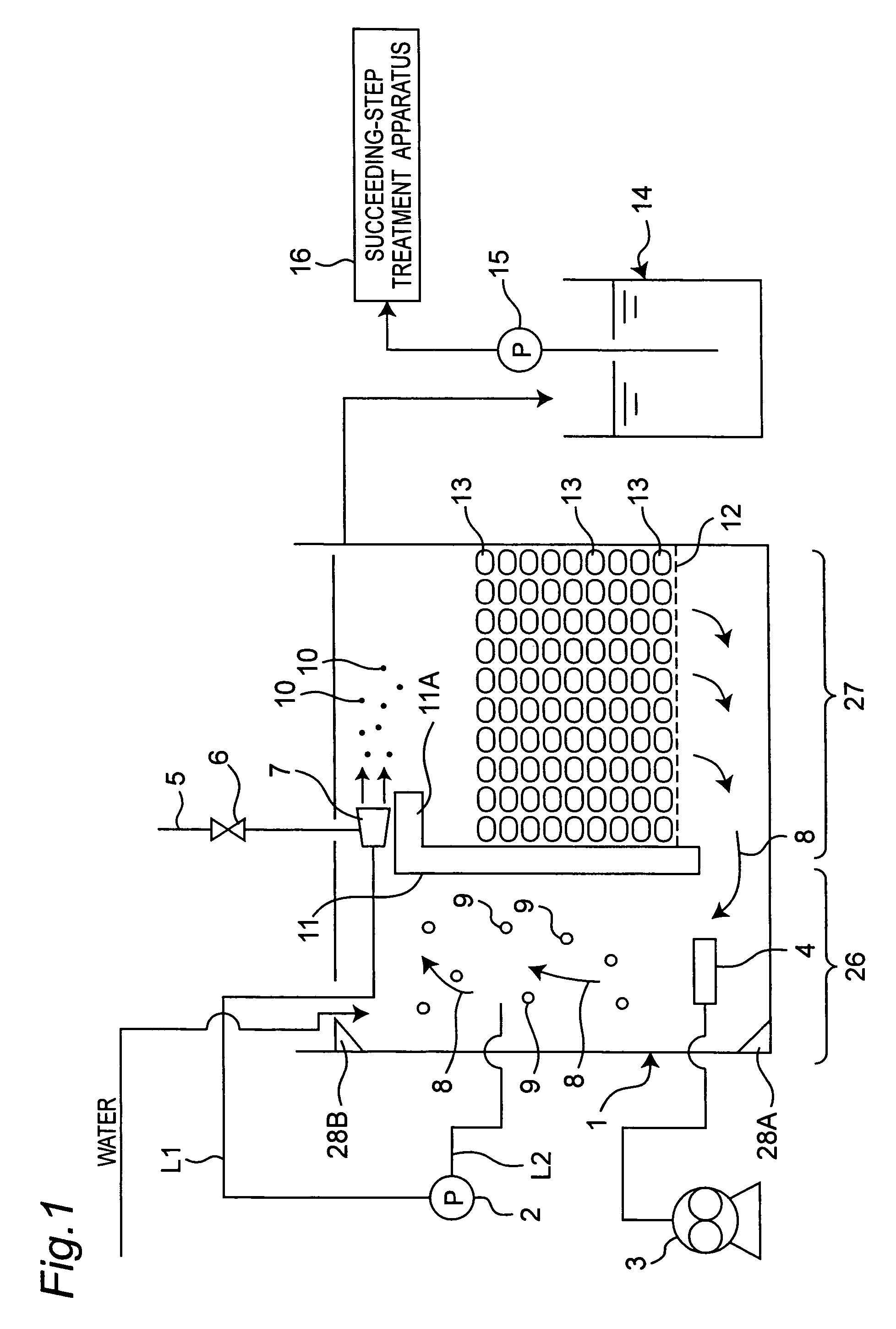
[0062]FIG. 1 is a view schematically showing a water treatment apparatus in a first embodiment of the present invention.

[0063]In FIG. 1, reference numeral 1 denotes a water treatment water tank, to which treatment water, i.e. water to be treated, is introduced.

[0064]The water treatment water tank 1 includes a water stream generation section 26 and a charcoal charging section 27, where the water stream generation section 26 and the charcoal charging section 27 are partitioned from each other by a hooked diaphragm 11. This hooked diaphragm 11 is spaced from a bottom of the water tank 1 with a specified distance, and the water stream generation section 26 and the charcoal charging section 27 are communicated with each other between the hooked diaphragm 11 and the bottom of the water tank 1.

[0065]In the water stream generation section 26, a diffuser 4 is placed at a lower portion, and the diffuser 4 is connected to a blower 3 placed outside the water tank 1. The diffuser 4 discharges bu...

second embodiment

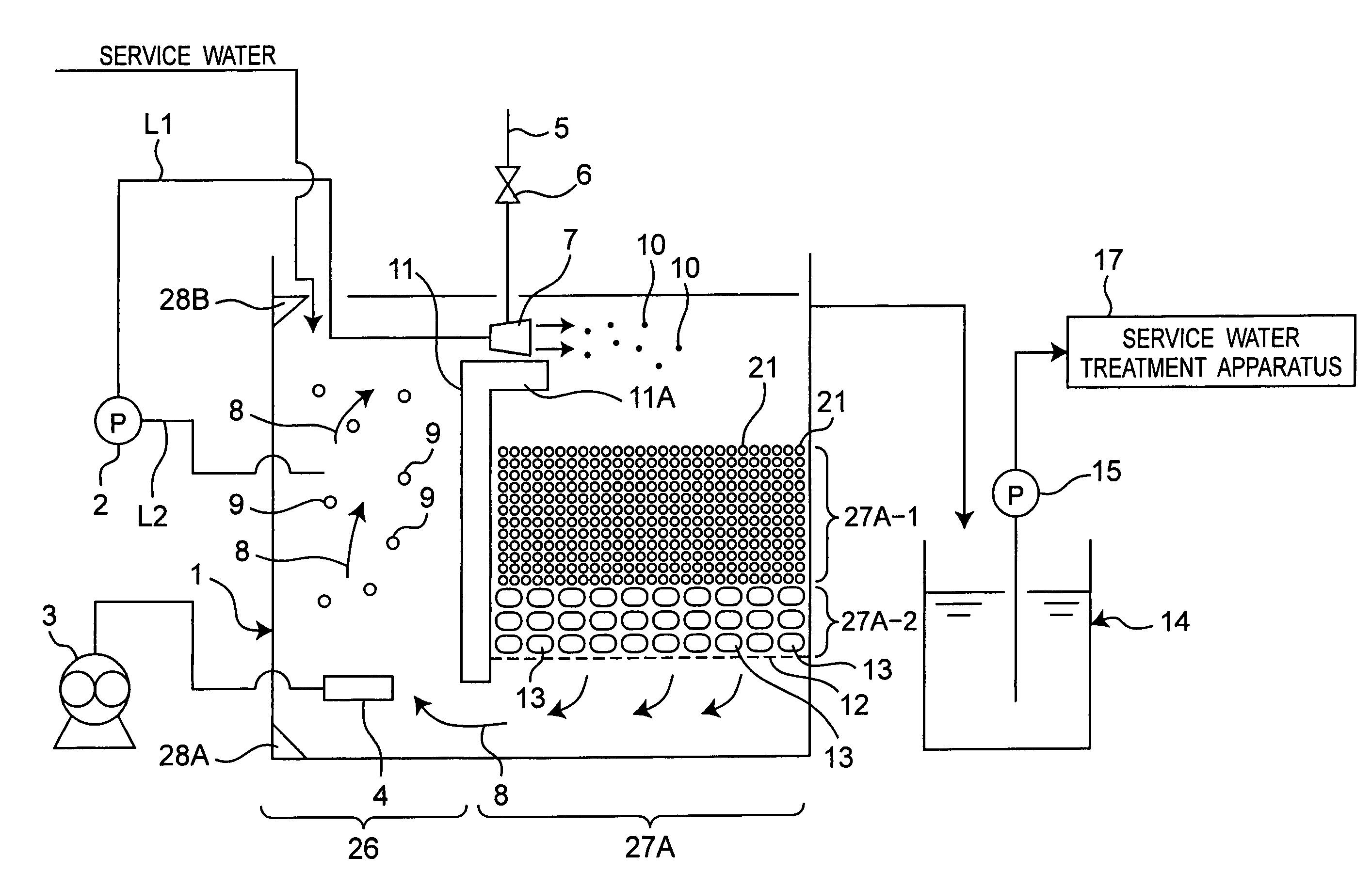
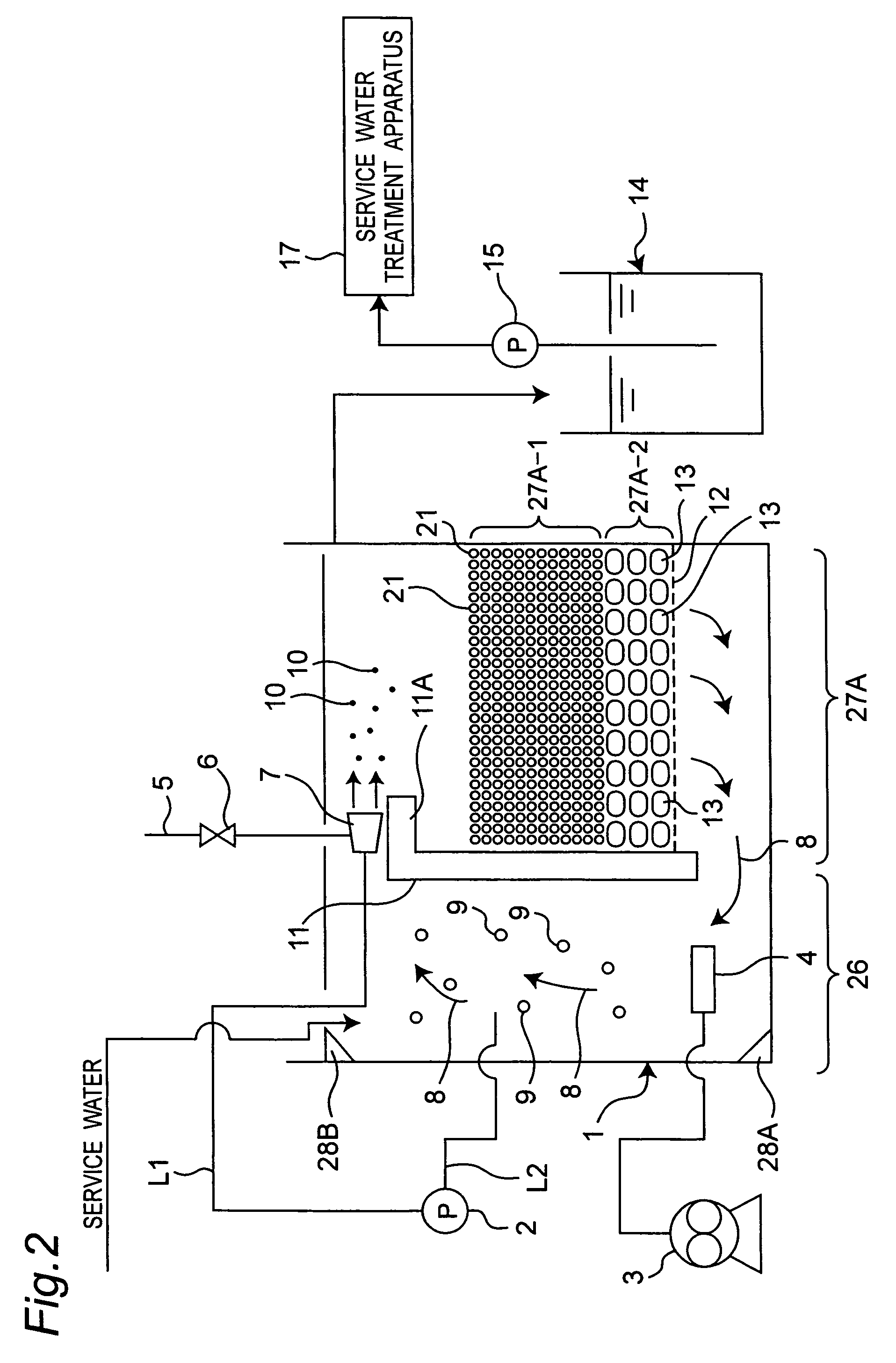
[0082]FIG. 2 shows a water treatment apparatus in a second embodiment of the present invention. In this second embodiment, the treatment water is service water. Also, the second embodiment differs from the foregoing first embodiment in that a charcoal charging section 27A having an upper charging section 27A-1 and a lower charging section 27A-2 is included instead of the charcoal charging section 27, and that a service water treatment apparatus 17 is included instead of the succeeding-step treatment apparatus 16. Therefore, in the second embodiment, the same parts as in the first embodiment are designated by the same reference numerals, their detailed description being omitted, and different parts from the first embodiment will be described below.

[0083]In the second embodiment, unlike the charcoal charging section 27 of the first embodiment, in which the total amount of charcoal is given by the wood charcoal 13, the charcoal charging section 27A of the water treatment water tank 1 h...

third embodiment

[0088]FIG. 3 shows a water treatment apparatus in a thrid embodiment of the present invention. The third embodiment differs from the foregoing first embodiment in that a charcoal charging section 27B is included instead of the charcoal charging section 27 of FIG. 1, a waste water treatment apparatus 18 is included instead of the succeeding-step treatment apparatus 16 of FIG. 1, and that the treatment water is waste water. Therefore, in the third embodiment, the same parts as in the first embodiment are designated by the same reference numerals, their detailed description being omitted, and different parts from the first embodiment will be described below.

[0089]In the third embodiment, the charcoal charging section 27B of the water treatment water tank 1 has wood charcoal 13, and reticulate tubes 22 placed adjacent to the wood charcoal 13. The wood charcoal 13 and the reticulate tubes 22 are placed on the net 12 transversely alternately.

[0090]In the case where the treatment water is ...


PUM

PropertyMeasurementUnit
temperaturesaaaaaaaaaa
diametersaaaaaaaaaa
diametersaaaaaaaaaa

Abstract

In a water treatment apparatus, microorganisms propagating on wood charcoal are activated by micro-nano bubbles contained in treatment water. Water treatment is carried out with the activated microorganisms propagated on the wood charcoal. Thereby, a stable treatment is achieved. Organic matters adsorbed by the wood charcoal are decomposed by the activated microorganisms propagated on the wood charcoal.

Description

CROSS-REFERENCE TO RELATED APPLICATIONS[0001]This nonprovisional application claims priority under 35 U.S.C. §119(a) on Patent Application No. 2005-336826 filed in Japan on 22 Nov. 2005, the entire contents of which are incorporated herein by reference.BACKGROUND OF THE INVENTION[0002]The present invention relates to a water treatment method and a water treatment apparatus, for example, to a water treatment method and a water treatment apparatus for use in semiconductor factories and liquid crystal factories.[0003]Treatment water contains organofluoric compounds as an example of compounds which are to be treated for water treatment. Organofluoric compounds are chemically stable substances. In particular, the organofluoric compounds have excellent properties from the viewpoints of heat resistance and chemical resistance, and therefore have been used for surface active agents or the like.[0004]However, the organofluoric compounds, because they are chemically stable, are less easily mi...

Claims


Application Information

Patent Timeline
Patent Type & Authority Patents(United States)
IPC IPC(8): C02F3/00
CPCC02F3/06C02F3/10C02F3/20C02F1/283Y02W10/10
Inventor YAMASAKI, KAZUYUKISAKATA, KAZUYUKICHUHJOH, KAZUMI
Owner SHARP KK
Why Eureka
Try Eureka