Deep water signal cable

a signal cable and deep water technology, applied in the field of deep water signal cables, can solve the problems of difficult stranding of cold-drawn copper wires to a conductor, and achieve the effect of a higher degree of flexibility

Inactive Publication Date: 2009-02-03
NEXANS
View PDF18 Cites 21 Cited by
  • Summary
  • Abstract
  • Description
  • Claims
  • Application Information

AI Technical Summary

Benefits of technology

[0020]A further advantage of the invention is that the signal cable has a higher degree of flexibility with respect to elongation.
is that the signal cable has a higher degree of flexibility with respect to elongation.

Problems solved by technology

As stranding of cold-drawn copper wires to a conductor is difficult because of the hardness of the copper wires a massive wire as the conductor is preferred.

Method used


Image

  • Deep water signal cable
  • Deep water signal cable
  • Deep water signal cable

Examples


Embodiment Construction

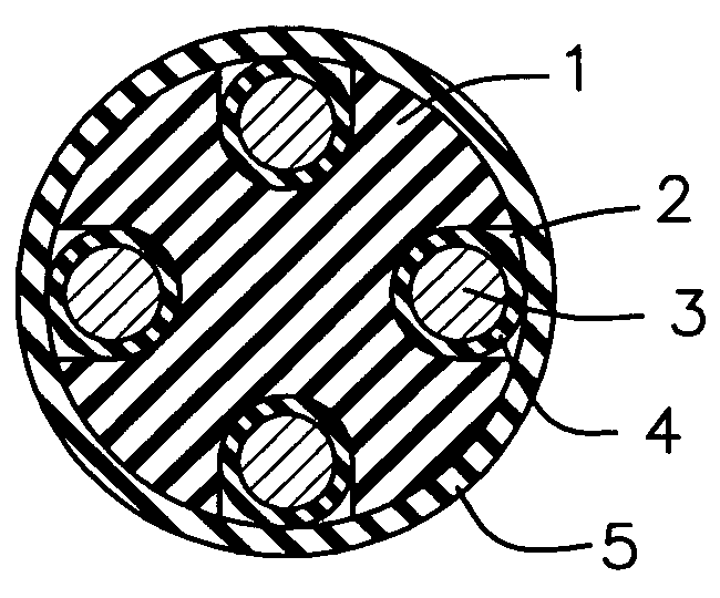
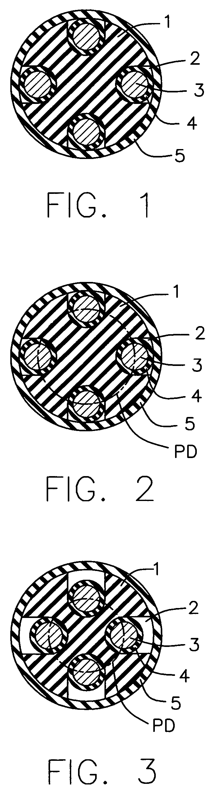
[0024]We refer first to FIGS. 1 to 3 showing the construction of a signal cable according to the invention.

[0025]A central element 1 made of a flexible or elastic material is provided with several grooves 2, which may be helical or longitudinal with respect to the central axis of the element 1. The element 1 is preferably made by extrusion of an elastic material such as natural or synthetic rubber. We prefer an elastomer such as EPDM. The grooves 2 may be arranged in the element during the extrusion step but may be cut into the extruded element 1.

[0026]Into each of the grooves 2 there are laid insulated electrical conductors which consist of a massive and cold drawn copper wire 3 and an insulating layer 4 of polyethylene or another insulating material. The element 1 with the insulated conductors within the grooves 2 is surrounded by a sheath 5 made of polyethylene or another insulated material used in the field of electric cables. The shown signal cable has four insulated conductors...


PUM

PropertyMeasurementUnit
depthsaaaaaaaaaa
depthaaaaaaaaaa
lengthaaaaaaaaaa

Abstract

An electrical signal cable having, at least two insulated conductors, wherein each of the insulated conductors is arranged in a groove (2) of a longitudinal central element (1) made of an elastic material which allows the insulated conductors to move in radial direction when the electrical signal cable is exposed to longitudinal tensile stress.

Description

RELATED APPLICATION[0001]This application is related to and claims the benefit of priority from Norwegian Patent Application No. 2005 0753, filed on Feb. 11, 2005, the entirety of which is incorporated herein by reference.[0002]1) Field of the Invention[0003]The present invention relates to improvements in umbilicals particularly umbilicals for use in deep water applications.[0004]2) Background Art[0005]An umbilical consists of a group of one or more types of elongated active umbilical elements, such as electrical cables, optical fiber cables or tubes, cabled together for flexibility and over-sheathed and / or armoured for mechanical strength and ballast.[0006]Umbilicals are used for transmitting power, signals and fluids to and from a subsea installation via the various elongated umbilical elements. An increasingly important use of umbilicals is the transmission of electrical power to electrical devices on the seabed, and depths of up to 2000 meters are common.[0007]Generally the ele...

Claims


Application Information

Patent Timeline
Patent Type & Authority Patents(United States)
IPC IPC(8): H01B7/00H01BH01B7/04
CPCH01B7/045
Inventor MJELSTAD, EINAR
Owner NEXANS
Why Eureka
Try Eureka