
Fully integrated terrestrial TV tuner architecture

Inactive Publication Date: 2009-02-03
WYSZYNSKI ADAM S
View PDF33 Cites 6 Cited by
  • Summary
  • Abstract
  • Description
  • Claims
  • Application Information

AI Technical Summary

Benefits of technology

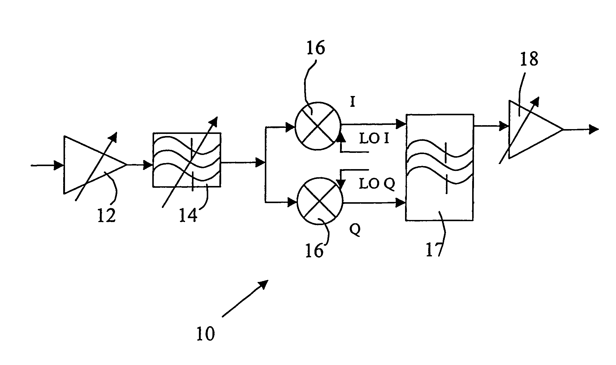
[0008]The proposed architecture introduces a tunable on-chip pre-filtering prior to a single down-conversion. This arrangement serves conserving the receiver power while simultaneously off-loading the front-end from the unwanted interferes. The image is rejected by 3 on-chip devices: the tunable RF bandpass, the complex-mixer and the complex IF bandpass filter. Overall image rejection is estimated to reach 65 dB, which is sufficient for this application. The ability to control the LNA's gain by 25-30 dB helps reduce the distortion level in case the input is overloaded. The VGA amplifier provides the remaining 50-55 dB of gain control.

Problems solved by technology

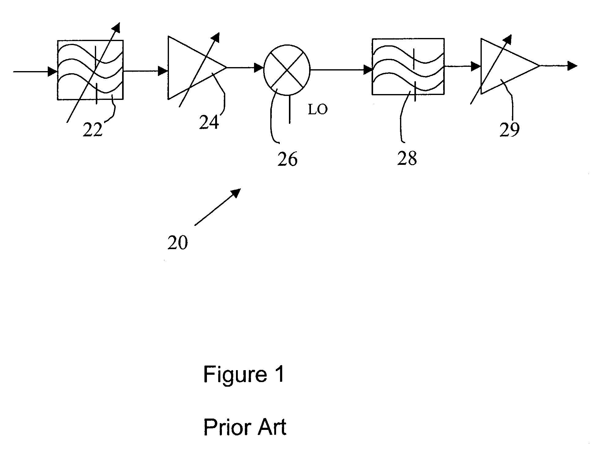
The main problem with this architecture is that the preselect tunable bandpass filter 22 is built as a discrete device using varactors as tunable capacitance elements and with its inductor coils manually adjusted during the manufacturing process.
Discrete varactors pose an additional problem since they need a separate 15V or more supply voltage for better tuning range.
Otherwise, the high-frequency noise would couple and totally distort the weak input TV signal.
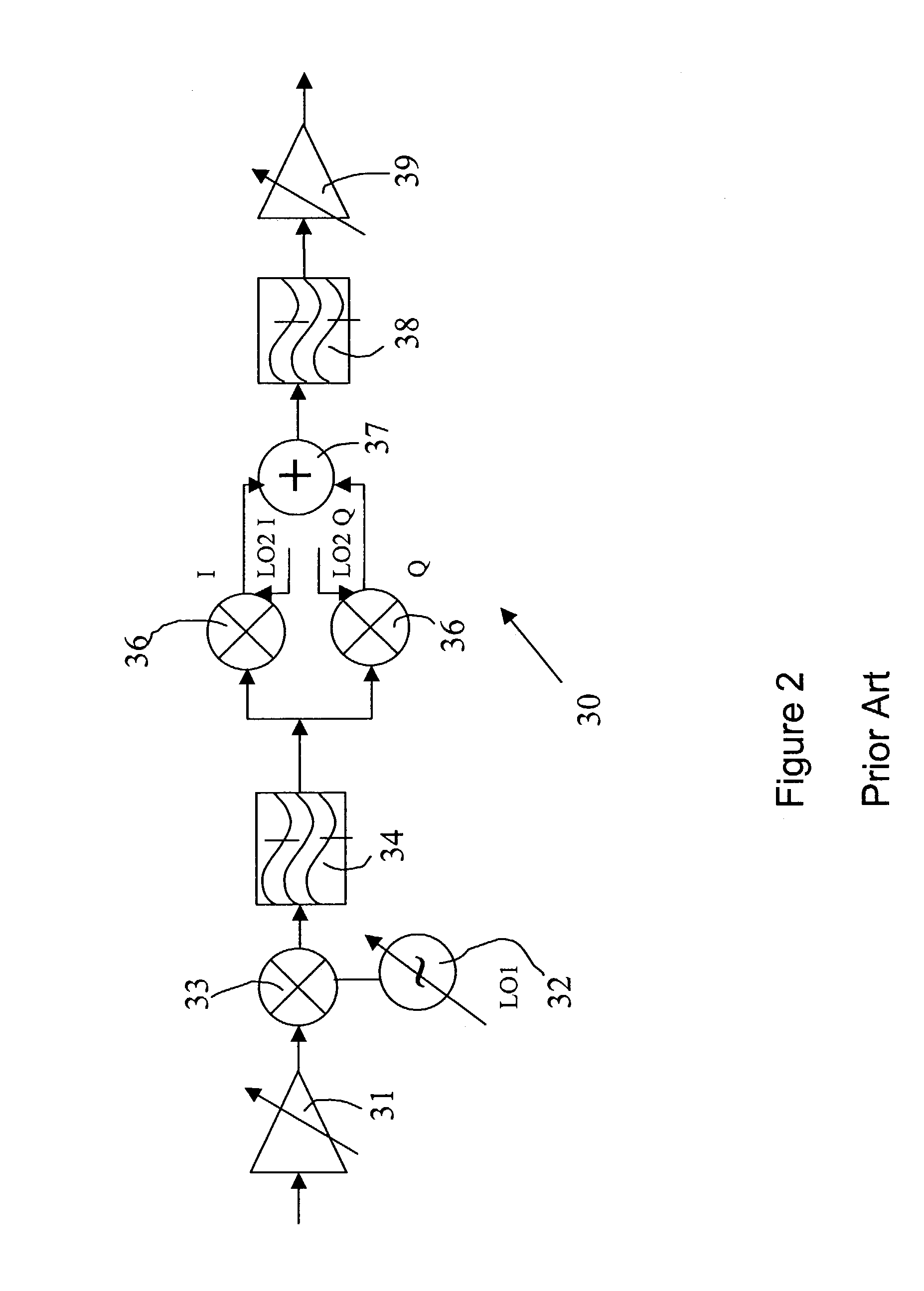
There are two main problems with this architecture.
First, it requires two external filters and several discrete components that complicate the board design and increase the cost of installing the tuner by approximately $2.
Secondly, since there is no prefiltering the strong interferers would load the input of the LNA, in particular the first mixer, and would severely degrade its intermodulation distortion performance.
Therefore, this architecture is not suitable for the terrestrial applications, but can be used in the cable environments where all signal powers are uniform.
Finally, since this architecture uses double-conversion and two external filters its power consumption is high.
The problem with this architecture is that since the LO is at the carrier frequency one of the mixer signal components is the dc-offset, which could severely degrade mixer's performance.

Method used


Image

  • Fully integrated terrestrial TV tuner architecture
  • Fully integrated terrestrial TV tuner architecture
  • Fully integrated terrestrial TV tuner architecture

Examples


Embodiment Construction

[0014]Referring to the FIG. 4, the present terrestrial tuner system is illustrated, and is generally identified by the numeral 10. The TV signal from the antenna enters the input of the low-noise amplifier (LNA) circuit 12, the output of which is connected to a tunable on-chip RF bandpass filter (RFBPF) circuit 14. The output of RFBPF circuit 14 is then connected to the two inputs of the complex mixer circuit 16, which consists of two identical mixers fed by identical input signals and two LO signals shifted by 90 degrees (LO I and LO Q). The complex mixer has two outputs I and Q. They enter two inputs of the complex IF bandpass filter (IFBPF) circuit 17. The I and Q outputs of the complex IFBPF circuit 17 are connected to the input of a variable gain amplifier (VGA) circuit 18.

[0015]LNA circuit 12 is required to have a low noise figure, very high linearity and ability of 25-30 dB gain control. RFBPF circuit 14 is realized as a tunable actively Q-enhanced passive LC filter demonstra...


PUM


Abstract

A TV tuner consisting of a least one low-noise amplifier, one mixer and one variable-gain amplifier plus two band-pass filters, the first of which is placed after low-noise amplifier and before the mixer, and the second of which is placed after mixer and before variable-gain amplifier. The filters are on-chip active devices equipped with on-chip frequency- and Q-tuning systems. The first band-pass filter is a real filter, such that its frequency response is symmetrical for positive and negative frequencies. The second band-pass filter is a complex filter, such that its frequency response has transmission for positive frequencies, but blocks negative frequencies. The low-noise amplifier includes gain control. The mixer is a complex-mixer consisting of two identical mixers driven by two local oscillator signals in quadrature.

Description

TECHNICAL FIELD OF THE INVENTION[0001]The present invention relates to TV receivers, or tuners such as those utilized for terrestrial (off-the-air) broadcast reception, and more particularly to a fully integrated implementation of the terrestrial TV tuner on a silicon chip.BACKGROUND OF THE INVENTION[0002]Currently, terrestrial tuners are built as hybrid devices using limited number of small ICs, metal shield can and external discrete components such as manually tuned coils and varactors. Significant progress has been made in integration of cable tuners. Most of these devices are integrated on one chip with two external ceramic or surface-acoustic wave (SAW) filters and a few several other discrete components.[0003]A reason for the slow progress in integration of a terrestrial TV tuner is the extremely demanding environment of off-the-air reception. The main problem is high power, out of band interferers such as cellular phone services that are close enough to the TV band. Another s...

Claims


Application Information

Patent Timeline
IPC IPC(8): H04N5/44H04N5/50
CPCH04N5/4446H04N21/4263H04N5/4401H04N21/426
Inventor WYSZYNSKI, ADAM S.
Owner WYSZYNSKI ADAM S
Learn More