Color filter with retardation layer and liquid crystal display

a retardation layer and liquid crystal display technology, applied in non-linear optics, instruments, optics, etc., can solve the problems of inability to achieve correct display, narrow visual angle issue presented, and substantial production, and achieve high contrast high quality display and effective restraining light leakage

Inactive Publication Date: 2009-02-03
DAI NIPPON PRINTING CO LTD
View PDF10 Cites 5 Cited by
  • Summary
  • Abstract
  • Description
  • Claims
  • Application Information

AI Technical Summary

Benefits of technology

[0009]The present invention has been achieved in view of the problems. The main object of the invention is to provide a color filter with a retardation layer, using a retardation layer as a C plate with a liquid crystal material used and a retardation layer as an A plate, capable of restraining the light leakage generation even in the case the visual angle is increased in the black display state, and a liquid crystal display.
[0010]As a result of the elaborate discussion on the circumstances, the present inventors have found out that the optimum retardation amount can be realized for each color by changing the thicknesses of the red, green and blue light transmissive patterns of the coloring layers respectively, and forming a retardation layer using a liquid crystal material on each color light transmissive pattern having the different thicknesses. Furthermore, they have found out that the light leakage generation of a purple color, or the like can be prevented by combining the retardation layer using the liquid crystal material and a retardation layer having the inverse dispersion characteristics even in the case the visual angle is increased in the black display state so as to complete the present invention.
[0011]That is, the present invention provides a color filter with a retardation layer comprising a base material, a coloring layer formed on the base material, with light transmissive patterns having different thicknesses according to each color formed in a plurality of rows, a first retardation layer formed on the coloring layer, made of a liquid crystalline polymer, having the optical axis perpendicular to a plane of the base material so as to function as a C plate, and a second retardation layer formed on a side opposite to a side with the coloring layer of the base material formed, or between the base material and the coloring layer, having an optical axis parallel to the plane of the base material so as to function as a positive A plate having the positive refractive index anisotropy, characterized in that the refractive index anisotropy of the second retardation layer in the visible light range becomes smaller with a shorter wavelength.

Problems solved by technology

Here, as the problems peculiar to the LCD, its narrow visual angle issue can be presented.
Therefore, the contrast inversion is generated so that the correct display cannot be achieved.
In particular, as to the positive C plate, it cannot be produced by the stretching process of a polymer so that it can substantially be produced only by using the liquid crystal material.
Here, in the case of the optical compensation over the entire visual light range at a certain observation angle, a problem is involved in that the retardation amount required to the retardation layer differs depending on every wavelength.
In this case, since the accurate optical compensation cannot be realized for the red color and the blue color, if the visual angle is made larger in the black display state, the light leakage of the red color and the blue color becomes conspicuous so that a problem arises in that it is observed for the reddish purple color, or the like.
However, the retardation layer in the JP-A No. 2003-315550 is produced by aligning the polymer so that a retardation layer using the liquid crystal material having the inverse dispersion characteristics has never been developed.

Method used


Image

  • Color filter with retardation layer and liquid crystal display
  • Color filter with retardation layer and liquid crystal display
  • Color filter with retardation layer and liquid crystal display

Examples


first embodiment

1. FIRST EMBODIMENT

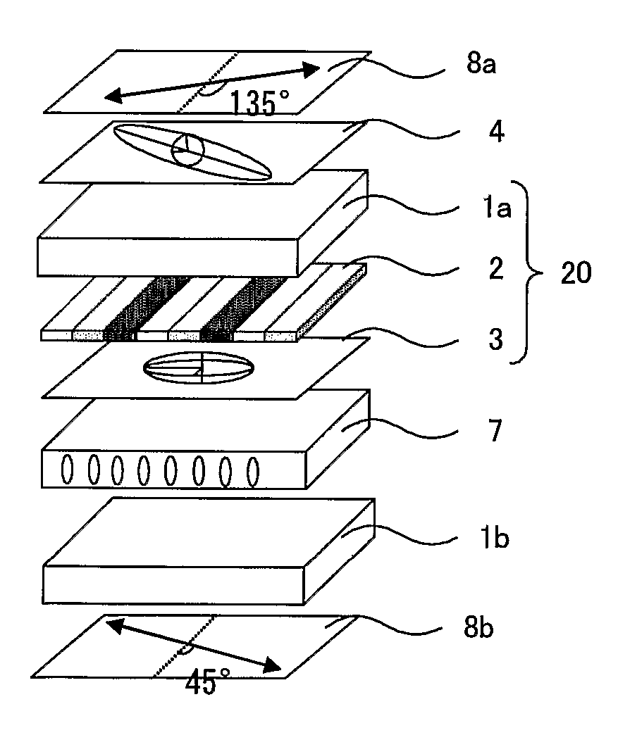
[0109]In the present invention, in the case the first retardation layer functions as a negative C plate, a liquid crystal display comprising a combination of the first retardation layer (negative C plate) and the second retardation layer (positive A plate) is provided. Thereby, the visual angle can be improved so that the optimum retardation amount can be obtained. Such a liquid crystal display of this embodiment is preferable as a liquid crystal display of for example the vertical alignment mode.

[0110]In the case the liquid crystal display of this embodiment is for example of the vertical alignment mode, the liquid crystal layer in the liquid crystal display functions as a positive C plate. Since the retardation amount of the liquid crystal layer tends to be larger than the retardation amount necessary for a positive C plate for the purpose of the optical compensation, in order to obtain a targeted retardation amount, it is preferable that the first retardation l...

second embodiment

2. SECOND EMBODIMENT

[0143]In the present invention, in the case the first retardation layer functions as a positive C plate, a liquid crystal display comprising a combination of the first retardation layer (positive C plate) and the second retardation layer (positive A plate) is provided. Thereby, the visual angle can be improved so that the optimum retardation amount can be obtained. Such a liquid crystal display of this embodiment is preferable as a liquid crystal display of the IPS (In Plane Switching) mode. Moreover, it can be used commonly for a liquid crystal display with two polarizing plates disposed in the crossed Nicol state.

[0144]In the case the liquid crystal display of this embodiment is of the IPS mode, since the refractive index anisotropy of the liquid crystal constituting the liquid crystal layer does not influence the retardation amount necessary for the optical compensation, the retardation amount of the liquid crystal layer needs not be considered for obtaining t...

example 1

Color Filter with a Retardation Layer

(Preparation of the Base Material)

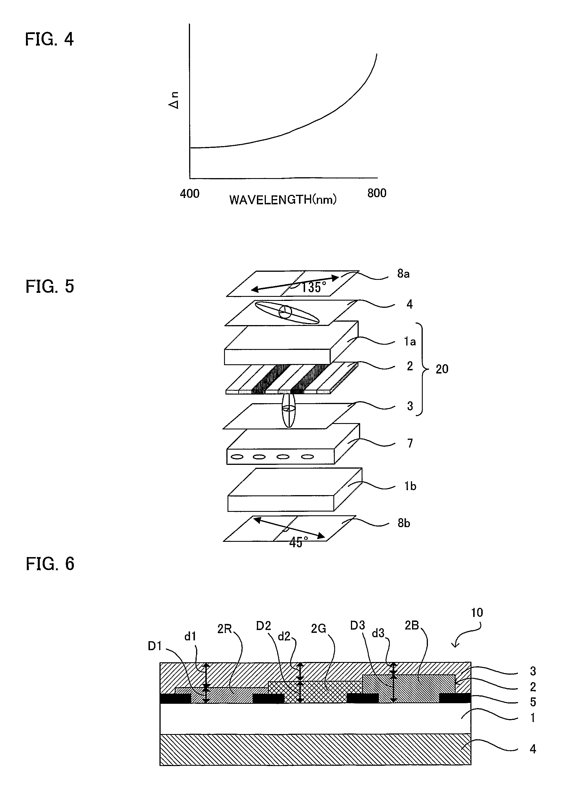
[0154]As a base material cleaned by applying an appropriate washing process, a glass substrate (1737 material, produced by Corning Inc.) was prepared.

(Preparation of a Coloring Layer Forming Coating Solution)

[0155]For the black matrix and light transmissive patterns of each color for red (R), green (G), blue (B), pigment dispersion type photo resists were used. The pigment dispersion type photo resists were prepared with pigments as the coloring agents by adding beads to a dispersion composition (containing a pigment, a dispersing agent and a solvent) so as to be dispersed for 3 hours with a disperser, and thereafter mixing the dispersion composition with the beads removed and a clear resist composition (containing a polymer, a monomer, an additive, an initiating agent and a solvent). The compositions of each pigment dispersion type photo resist used for the black matrix and the light transmissive patterns of eac...


PUM

PropertyMeasurementUnit
pole angleaaaaaaaaaa
thicknessaaaaaaaaaa
thicknessaaaaaaaaaa

Abstract

The main object of the present invention is to provide a colour filter with a retardation layer, capable of minimizing light leakage even in the case the visual angle is large in the black display state, for a liquid crystal display. The present invention achieves the object by providing a colour filter with a retardation layer comprising a substrate, a colour layer formed on the substrate, being arranged in a plurality of rows having different thicknesses according to each colour, a first retardation layer formed on the colour layer, made of a liquid crystalline polymer, having its optic axis perpendicular to a plane of the substrate so as to function as a C plate, and a second retardation layer the colour layer, wherein the optic axis of the second retardation layer is arranged parallel to the plane of the substrate so as to function as a positive Aplate with positive refractive index anisotropy, and the refractive index anisotropy of the second retardation layer in the visible light range decreases at shorter wavelengths inverse dispersion characteristics.

Description

TECHNICAL FIELD[0001]The present invention relates to a color filter with a retardation film having a retardation layer for improving the visual angle, suitable for a liquid crystal display for the color display, and a liquid crystal display.BACKGROUND ART[0002]Owing to the characteristics of the liquid crystal display (hereinafter it is also referred to as the LCD) for the color display such as the thin shape, the light weight, the power consumption saving and the flickerless, the market thereof has rapidly been expanded mainly for the laptop type personal computers. Recently, as a part of such a display apparatus for the personal computers, demand for the monitors for the desktop type personal computers larger than the laptop type personal computers has been generated. Moreover, not only for the personal computer application, the LCD has been utilized also for the televisions, for which the cathode ray tube (CRT) has conventionally been the mainstream.[0003]Here, as the problems p...

Claims


Application Information

Patent Timeline
Patent Type & Authority Patents(United States)
IPC IPC(8): G02F1/1335
CPCG02F1/133514G02F1/13363G02F1/133634G02F2001/133565G02F2001/133633G02F2001/133637G02F2413/02G02F2413/09G02F2413/11G02F2413/13G02F1/133565G02F1/133631G02F1/133633G02F1/133637G02F1/1335
Inventor MORIYA, NORIHISA
Owner DAI NIPPON PRINTING CO LTD
Why Eureka
Try Eureka