Optimized helix angle rotors for Roots-style supercharger

a supercharger and rotor technology, applied in the direction of rotary or oscillating piston engines, rotary piston engines, engine lubrication, etc., can solve the problems of pulsation, noise, turbulence, etc., to improve the overall operating efficiency of the blower, improve thermal efficiency, and reduce input power

Active Publication Date: 2009-02-10
EATON INTELLIGENT POWER LTD
View PDF8 Cites 63 Cited by
  • Summary
  • Abstract
  • Description
  • Claims
  • Application Information

AI Technical Summary

Benefits of technology

[0011]Accordingly, it is an object of the present invention to provide a Roots-type blower in which the rotors and lobes are designed to provide improved overall operating efficiency of the blower, and especially, improved thermal efficiency, and reduced input power.
[0012]It is a related object of the present invention to provide an improved method of designing a rotor for a Roots-type blower which achieves the above-stated object while at the same time permitting a higher speed of rotation of the rotors, thus providing an improved “matching” of the lobe mesh linear velocity to the incoming air linear velocity.
[0013]It is another object of the present invention to provide such an improved method of designing a rotor for a Roots-type blower wherein the resulting blower can be operated at a somewhat higher pressure ratio than the conventional, prior art blower.
[0014]It is a still further object of the present invention to provide such an improved method of designing a rotor for a Roots-type blower wherein it is possible to vary the extent of the backflow seal time to effectively produce dynamic internal compression within the blower, and also, to determine the rotor twist angle which will provide a maximum, ideal helix angle for a given design, without producing an internal leak which would significantly reduce the low speed performance of the blower.

Problems solved by technology

However, as such blowers were further developed, and the applications for such blowers became more demanding, it became conventional practice to provide rotors having three lobes, with the lobes being twisted.
Such a mismatch of V1 and V3 will cause pulsations, turbulence and noise, (and creating such requires “work”), all of which are serious disadvantages on an engine supercharger, rotating at speeds of as much as 15,000 to about 18,000 rpm.

Method used


Image

  • Optimized helix angle rotors for Roots-style supercharger
  • Optimized helix angle rotors for Roots-style supercharger
  • Optimized helix angle rotors for Roots-style supercharger

Examples


Embodiment Construction

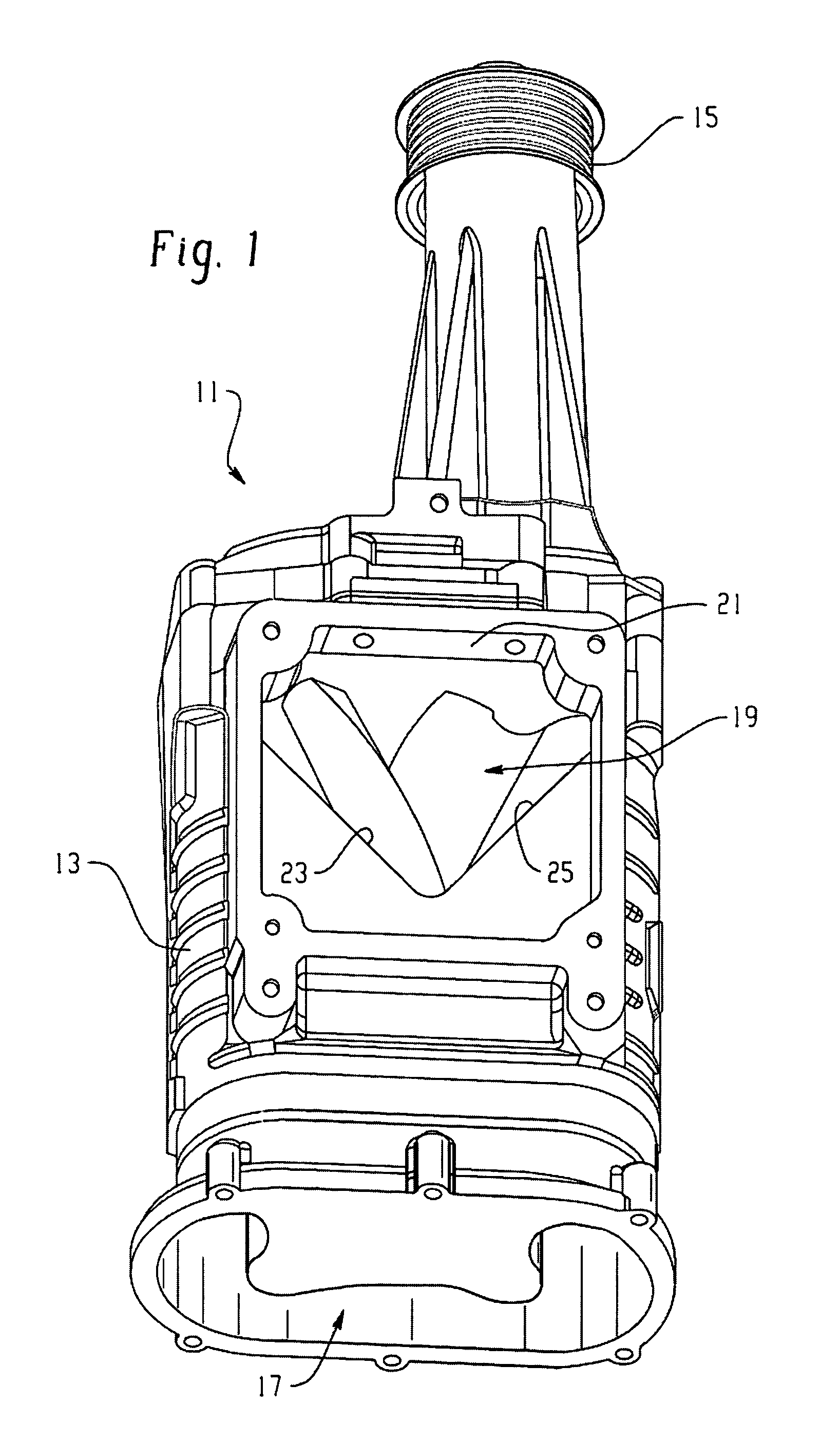
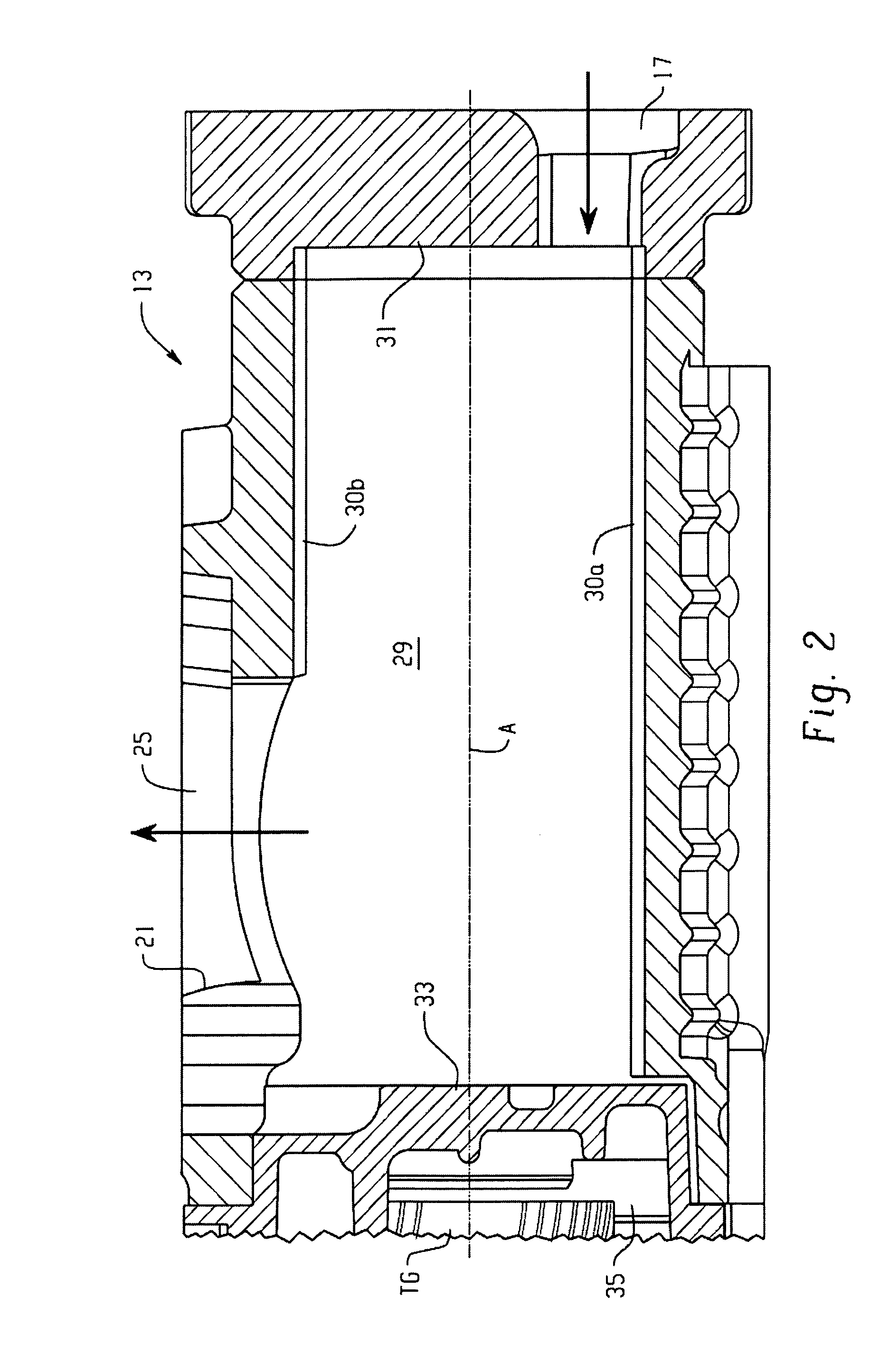
[0026]Referring now to the drawings, which are not intended to limit the invention, FIG. 1 is an external, perspective view of a Roots-type blower, generally designated 11 which includes a blower housing 13. As was described in the background of the disclosure, the blower 11 is preferably of the rear inlet, radial outlet type and therefore, the mechanical input to drive the blower rotors is by means of a pulley 15, which would be disposed toward the forward end of the engine compartment. Toward the “lower” end of the view in FIG. 1, the blower housing 13 defines an inlet port, generally designated 17.

[0027]The blower housing 13 also defines an outlet port, generally designated 19 which, as may best be seen, in FIG. 1, is generally triangular including an end surface 21 which is generally perpendicular to an axis A (see FIG. 2) of the blower 11, and a pair of side surfaces 23 and 25 which will be referenced further subsequently. It is a requirement in such a blower that the inlet por...


PUM


Abstract

A method of designing rotors for a Roots blower comprising a housing having cylindrical chambers, the housing defining an outlet port (19). The blower includes meshed, lobed rotors (37,39) disposed in the chambers, each rotor including a plurality N of lobes (47,49), each lobe having first (47a,49a) and second (47b,49b) axially facing end surfaces. Each lobe has its axially facing surfaces defining a twist angle (TA), and each lobe defines a helix angle (HA). The method of designing the rotor comprises determining a maximum ideal twist angle (TAM) for the lobe as a function of the number N of lobes on the rotor, and then determining a helix angle (HA) for each lobe as a function of the maximum ideal twist angle (TAM) and an axial length (L) between the end surfaces of the lobe. A rotor designed in accordance with this method is also provided.

Description

BACKGROUND OF THE DISCLOSURE[0001]The present invention relates to Roots-type blowers, and more particularly, to such blowers in which the lobes are not straight (i.e., parallel to the axis of the rotor shafts), but instead, are “twisted” to define a helix angle.[0002]Conventionally, Roots-type blowers are used for moving volumes of air in applications such as boosting or supercharging vehicle engines. As is well known to those skilled in the art, the purpose of a Roots-type blower supercharger is to transfer, into the engine combustion chambers, volumes of air which are greater than the displacement of the engine, thereby raising (“boosting”) the air pressure within the combustion chambers to achieve greater engine output horsepower. Although the present invention is not limited to a Roots-type blower for use in engine supercharging, the invention is especially advantageous in that application, and will be described in connection therewith.[0003]In the early days of the manufacture...

Claims


Application Information

Patent Timeline
Patent Type & Authority Patents(United States)
IPC IPC(8): F01C1/08F01C1/24
CPCF04C18/084F04C18/16F04C18/18F02B33/38F04C18/126F04C29/12F04C2240/30F04C2250/20
Inventor SWARTZLANDER, MATTHEW G.
Owner EATON INTELLIGENT POWER LTD
Why Eureka
Try Eureka