Variable gain amplifying circuit

a gain amplifying circuit and variable gain technology, applied in the direction of amplifiers, amplification control details, positive-feedback circuit arrangements, etc., can solve the problem of very limited gain range of each stage, and achieve the effect of widening the total gain range, widening the gain range, and quick adjustment of gain

Active Publication Date: 2009-02-10
MEDIATEK SINGAPORE PTE LTD SINGAPORE
View PDF4 Cites 1 Cited by
  • Summary
  • Abstract
  • Description
  • Claims
  • Application Information

AI Technical Summary

Benefits of technology

[0012]It is an object of the present invention to provide a variable gain amplifying circuit having a wide gain range in each stage and providing a rapidly adjustable gain in an automatic gain control system.
[0015]In contrast to the prior art, the variable gain amplifying circuit of the present invention is capable of providing a rapidly adjustable gain and a wider gain range in each stage. The variable gain amplifying circuit of the present invention can vary the emitter current IE and the resistance RE simultaneously according to the variation of the control voltage Vctrl. Therefore, the variable gain amplifying circuit of the present invention is capable of preventing signal from being clipped during low gain and providing a wider total gain range with fewer stages.

Problems solved by technology

It causes that the gain range of each stage is very limited.

Method used


Image

  • Variable gain amplifying circuit
  • Variable gain amplifying circuit
  • Variable gain amplifying circuit

Examples


Embodiment Construction

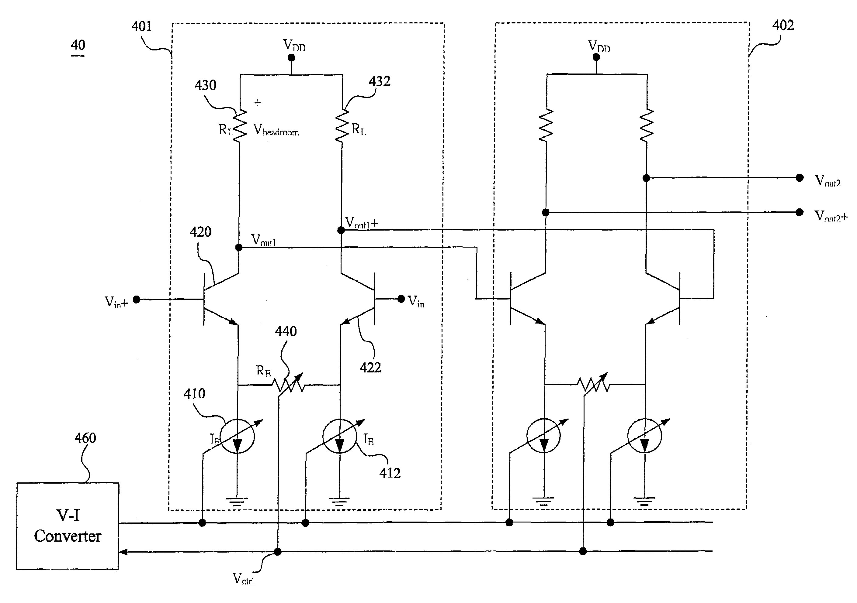
[0021]FIG. 3 is a schematic block diagram illustrating an automatic gain control system 30. The automatic gain control system 30 comprises an automatic gain controller 310 and a variable gain amplifying circuit 40. The automatic gain controller 310 generates a control voltage Vctrl to control the gain of the variable gain amplifying circuit 40. The variable gain amplifying circuit 40 receives a differential pair of input signals Vin+ and Vin− to amplify the same with a variable gain corresponding to the control voltage Vctrl, then the variable gain amplifying circuit 40 outputs a differential pair of amplified signals Vout+ and Vout−.

[0022]FIG. 4 is a circuit diagram illustrating the variable gain amplifying circuit 40 in accordance with the present invention. The variable gain amplifying circuit 40 of the present embodiment comprises two stages, a first stage 401 and a second stage 402 with a common voltage-to-current converter 460. The first stage 401 comprises two BJTs 420, 422, ...


PUM


Abstract

A variable gain amplifying circuit comprises two stages, a first stage and a second stage with a common voltage-to-current converter. Each stage comprises two BJTs, two voltage controlled current sources, a variable resistor with a variable resistance, and the common voltage-to-current converter. The two BJTs construct a differential amplifier for amplifying a pair of differential signals. The variable resistor with the variable resistance is connected between the emitters of the two BJTs wherein the variable resistance of the variable resistor is represented as RE. The variable resistance RE is controlled by a control voltage Vctrl. The two voltage controlled current sources are respectively connected between the corresponding emitter of BJTs and ground. The currents respectively through the voltage controlled current sources are equal to each other and represented as IE. The current IE is controlled by the common voltage-to-current converter according the control voltage Vctrl. The variable resistance RE and the current IE of the voltage controlled current sources can be varied simultaneously by the control voltage Vctrl so as to rapidly adjust the gain of the variable gain amplifying circuit.

Description

FIELD OF THE INVENTION[0001]The present invention relates to a variable gain amplifying circuit, more particularly, to a variable gain amplifying circuit of which each stage has a wide gain range and a rapidly adjustable gain.BACKGROUND OF THE INVENTION[0002]Automatic gain control (AGC) systems are generally used in many kinds of electronic products, such as communication products, memory storage products, wireless transceivers, etc. The automatic gain control system comprises a variable gain amplifier (VGA) to amplify the received signals whose amplitudes may vary within a wide range so that amplified signals output from the variable gain amplifier can have a substantially constant amplitude.[0003]FIG. 1 is a circuit diagram illustrating a conventional variable gain amplifying circuit 10. The variable gain amplifying circuit 10 is provided for amplifying the differential input signals Vin+ and Vin−. The variable gain amplifying circuit 10 comprises a plurality of stages, such as a ...

Claims


Application Information

Patent Timeline
Patent Type & Authority Patents(United States)
IPC IPC(8): H03F3/45
CPCH03F3/45197H03G1/0029H03F2203/45244H03F2203/45466H03F2203/45492H03F2203/45494H03F2203/45652
Inventor LIEN, WEE LIANGDHARMALINGGAM, RAWINDERWONG, TEN VOON
Owner MEDIATEK SINGAPORE PTE LTD SINGAPORE
Why Eureka
Try Eureka