
Artificial spinal disc replacement system and method

a technology of artificial spinal discs and discs, applied in the field of artificial spinal disc replacements, can solve the problems of limiting range-of-motion (rom), affecting the function of patients, and significant pain and suffering of patients so affected, so as to preserve spinal range-of-motion (rom) and flexibility, eliminate nerve root and/or spinal cord compression, and preserve spinal rom and flexibility

Active Publication Date: 2009-02-17
CARVER DONNA JEAN +2
View PDF31 Cites 46 Cited by
  • Summary
  • Abstract
  • Description
  • Claims
  • Application Information

AI Technical Summary

Benefits of technology

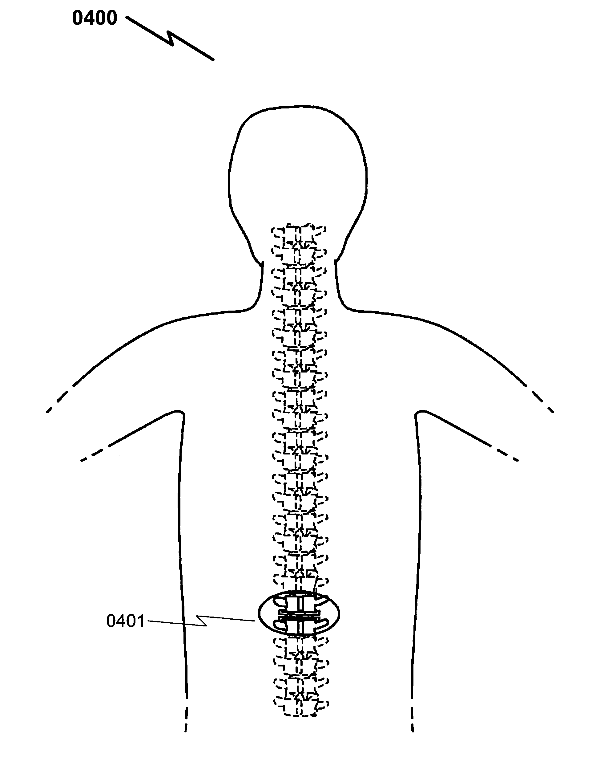
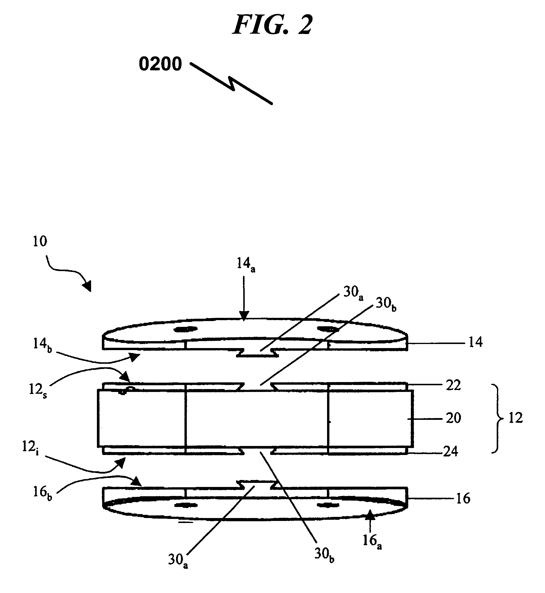
"The present invention is a spinal disc replacement system that includes an upper bracket and a lower bracket that are connected together. The upper bracket has spring-loaded vertical contact surfaces that provide a rigid connection between the implant and the skeletal structure. The system also includes fastening means for attaching the spring to the upper bracket, such as screws or nuts. The system is designed to be installed using laparoscopic surgery and provides maximum surface area for adhesion to the bone. The invention also includes perspective views of the installed system and exploded views of the upper bracket. The technical effects of the invention include improved spinal column stability, reduced surgery invasiveness, and improved patient outcomes."

Problems solved by technology

Unfortunately, injury to the spine or spinal discs is a common occurrence in the workplace, resulting in significant pain and suffering for patients so afflicted.
Americans spend about USD$50 billion each year on low back pain, which represents the most common cause of job-related disability and lost work days in the United States.
Lumbar spinal fusion surgery is a common surgical treatment for low back pain or degenerative disc disease and is often effective in reducing pain, but it limits range-of-motion (ROM) and may transfer extra stress to discs above and below the fusion site.
With aging, the discs dehydrate and thin, resulting in a loss of disc height.
During motions, the joint can be injured with stresses of only 6-7 kg and, in some cases, the disc could be injured and in others, a ligament might be injured.
The disc becomes thinner and more brittle and even cracked in places and they lose their elasticity and water content thus becoming less of a spinal stabilizer.
It is a prevalent misconception that most disc herniations result from a single event or trauma, microtrauma, primarily from repetitive flexion and rotation movement, leads to a degenerative cascade that frequently results in a herniated nucleus pulposus.
Neural compression or irritation may precipitate motor weakness, reduced reflexes, and sensory loss.
Some surgeons have moved to using an anterior approach (ALIF), but the ALIF cannot stand alone to withstand the forces of daily patient use and surgeons have found that, in order to prevent collapse or lack of fusion altogether, they have to protect the graft with posterior instrumentation which is placed either on the same day of surgery or in another procedure.

Method used


Image

  • Artificial spinal disc replacement system and method
  • Artificial spinal disc replacement system and method
  • Artificial spinal disc replacement system and method

Examples


embodiment (

Generalized Method Embodiment (4000)

[0179]The present invention may incorporate a method of using the system as described in an application wherein a spinal disc is replaced within a patient. This method (4000) may be generally described as follows:

[0180]A method of artificial spinal disc replacement within a patient's spinal column, said method comprising:[0181](1) Laparoscopically creating an incision into a portion of said patient's back at the point of spinal disc replacement on said spinal column (4001);[0182](2) Inserting an upper bracket through said incision, said upper bracket further comprising springs, spring fasteners, and upper vertebral contact surface (4002);[0183](3) Inserting a lower bracket through said incision, said lower bracket further comprising lower vertebral contact surface and spring guide track (4003);[0184](4) Mating said upper bracket springs into said lower bracket spring guide track (4004);[0185](5) Fixing said upper bracket upper vertebral contact su...


PUM


Abstract

An artificial spinal disc implant system for intervertebral disc replacement (0810) is disclosed which is formed from an upper (0801) and lower (0802) bracket which mate to upper and lower spinal vertebrae via upper (0831) and lower (0832) vertebral contact surfaces on the upper (0801) and lower (0802) brackets. The upper (0801) and lower (0802) brackets are joined together via springs (0811) connected to the upper bracket (0801) which rest in spring guide tracks (0812) on the lower bracket. The springs (0811) are connected to the upper bracket (0801) via the use of spring fasteners (0821, 0822). The upper (0801) and lower (0802) brackets may be installed in sections (0851, 0861, 0871, 0852, 0862, 0872) using laparoscopic surgical techniques and are attached to upper / lower spinal vertebrae respectively via adhesive means applied using injection holes / ports (0841, 0842) in the upper (0801) and lower (0802) brackets respectively.

Description

CROSS REFERENCE TO RELATED APPLICATIONS[0001]Applicant claims benefit pursuant to 35 U.S.C. § 119 and hereby incorporates by reference Provisional Patent Application for “ARTIFICIAL SPINAL DISC REPLACEMENT SYSTEM AND METHOD”, Ser. No. 60 / 725,460, filed Oct. 10, 2005, and submitted to the USPTO with Express Mail on Oct. 10, 2005 with tracking number ER618466616US.PARTIAL WAIVER OF COPYRIGHT[0002]All of the material in this patent application is subject to copyright protection under the copyright laws of the United States and of other countries. As of the first effective filing date of the present application, this material is protected as unpublished material.[0003]However, permission to copy this material is hereby granted to the extent that the copyright owner has no objection to the facsimile reproduction by anyone of the patent documentation or patent disclosure, as it appears in the United States Patent and Trademark Office patent file or records, but otherwise reserves all copy...

Claims


Application Information

Patent Timeline
Patent Type & Authority Patents(United States)
IPC IPC(8): A61F2/44
CPCA61F2/442A61F2002/30187A61F2002/30433A61F2002/30441A61F2002/30571A61F2002/30574A61F2002/30604A61F2002/30772A61F2002/4631A61F2220/0041A61F2230/0034A61F2310/00023A61F2310/00029
Inventor CARVER, DONNA JEANBARRIE, CHAD ANTHONYHERRERA, JOHN DAVID
Owner CARVER DONNA JEAN
Learn More