System and method for pressure wave transmission and measurement

Inactive Publication Date: 2009-02-17
NEW JERSEY INSTITUTE OF TECHNOLOGY
View PDF3 Cites 12 Cited by
  • Summary
  • Abstract
  • Description
  • Claims
  • Application Information

AI Technical Summary

Benefits of technology

[0008]As ultrasonic transducers are operated at a relatively high nominal frequency and quality factor, feedforward strategy is among the most efficient means for generating the low transient acoustic pulses. In an embodiment, a digital signal processor and a field programmable gate array may synthesize the transmitter drive signal to emit low transient pulses w

Problems solved by technology

However, due to the narrow transducer bandwidth, an ultrasonic transmitter driven by a conventional Rectangular Modulation Pulse (RMP) drive signal ten

Method used


Image

  • System and method for pressure wave transmission and measurement
  • System and method for pressure wave transmission and measurement
  • System and method for pressure wave transmission and measurement

Examples


embodiment

Topology Measurement Embodiment

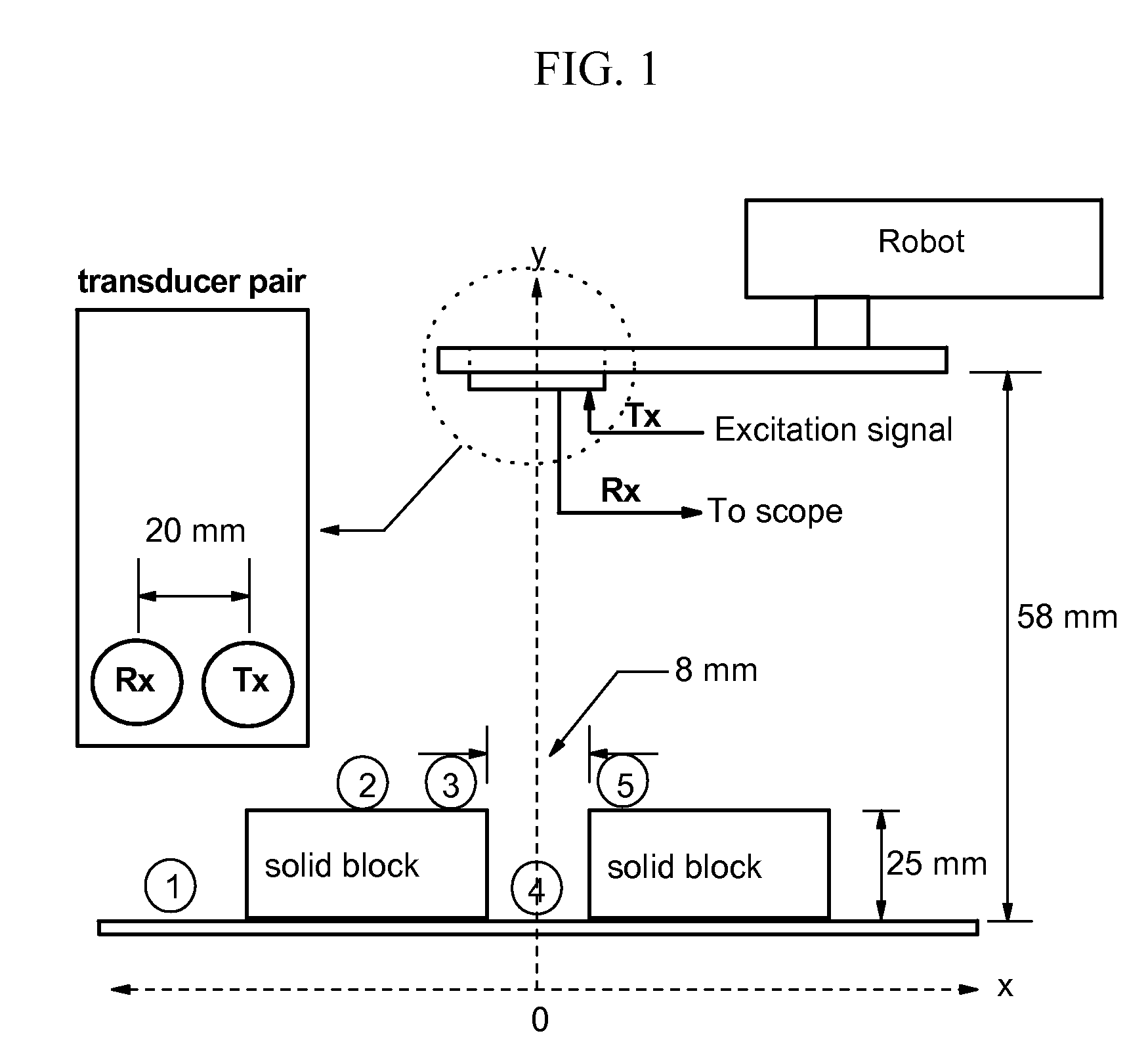
[0071]In this embodiment, the transmission of pressure waves and measurement of waves echoing off various surfaces may be employed to measure the surface topology of one or more objects. In the embodiment of FIG. 1, a system and method in accordance with an embodiment of the invention are employed to measure the characteristics (such as width and depth) of a notch between two solid blocks. However, the inventive principles disclosed herein may be employed to measure many variations in surface topology other than a notch between two blocks. More generally, any variation in surface topology that modifies the timing, direction, and / or amplitude (or other pertinent factor) of a reflected pressure wave (in the case of an echo transmission embodiment) and / or of a transmitted pressure wave (in the case of an axial transmission embodiment) is preferably measurable using the systems and methods disclosed herein. Moreover, other configurations of the equipment s...


PUM


Abstract

A system and method for measurement are disclosed which may include providing an input command signal; convolving the input command signal with a plurality of impulse signals to produce a transducer drive signal; and activating a first pressure transducer with the drive signal to transmit a pressure wave output from the transducer.

Description

CROSS-REFERENCE TO RELATED APPLICATIONS[0001]This application claims the benefit of U.S. Provisional Patent Application Ser. No. 60 / 836,628, filed Aug. 9, 2006, entitled “Enhancing Ultrasonic Imaging With Low Transient Pulse Shaping”, the entire disclosure of which is incorporated herein by reference.FIELD OF THE INVENTION[0002]This invention relates in general to pressure wave based transmission and measurement and in particular to improving the resolution of pressure wave based measurement systems.BACKGROUND OF THE INVENTION[0003]The bracketed information herein refers to documents listed at the end of this document, which are referred to by reference number, author, and year of publication.[0004]Ultrasonic ranging systems have been widely used in applications such as mobile robots, surface / subsurface feature detection, medical imaging, etc. [Manthey, 1992 (R12)] [Ashley, 2001 (R3)]. The primary performance factors of such ranging systems include: resolution, power, and scattering...

Claims


Application Information

Patent Timeline
IPC IPC(8): H04B1/02
CPCG01S7/52004G01S7/524G01S7/539
Inventor CHANG, TIMOTHYCHENG, BIAO
Owner NEW JERSEY INSTITUTE OF TECHNOLOGY
Why Eureka
Try Eureka