High-power PIN diode switch

a high-power, pin-type technology, applied in the direction of diodes, electronic switching, pulse techniques, etc., can solve the problems of considerable thermal problems of multi-turn coils, the reliability and stability of switches can influence the performance of plasma processing equipment, and the loss factor of coils is very low

Active Publication Date: 2009-03-03
AES GLOBAL HLDG PTE LTD
View PDF16 Cites 54 Cited by
  • Summary
  • Abstract
  • Description
  • Claims
  • Application Information

AI Technical Summary

Problems solved by technology

Furthermore, the reliability and stability of the switch can impact the performance of plasma processing equipment.
In VHF range, such a high voltage usually results in considerable thermal problems for the multi-turn coils.
To handle such a high RF voltage, the coils need a very low loss factor (hence big size) and require a complex cooling system.
Another drawback of the coils is low temperature stability and long-term mechanical instability if expensive mechanical constructions are not used.
These factors limit using lumped circuit elements for high-power and high-reliability systems.
But switches employing quarter-wavelength, resonant transmission lines have significant drawbacks.
All those changes increase RF energy losses in the line.
Those effects can impose a practical limit on the extent to which the size of the stripline can be compacted.

Method used


Image

  • High-power PIN diode switch
  • High-power PIN diode switch
  • High-power PIN diode switch

Examples


Embodiment Construction

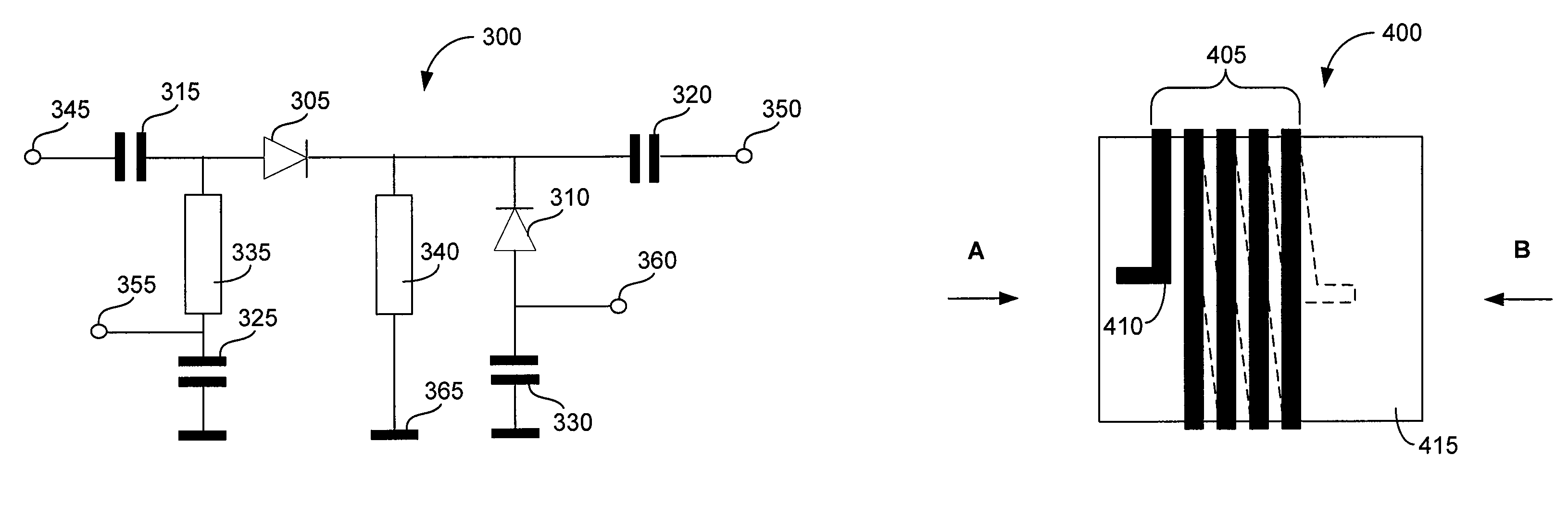
[0026]In one illustrative embodiment of the invention, a PIN diode single-pole, single-throw (SPST) switch is provided that has low cost, high stability and reliability, and small size. The PIN diode switch comprises a series PIN diode and direct-current (DC) biasing circuit in which DC-conducting and radio-frequency (RF)-isolating elements are microstrip-line-type, folded, quarter-wavelength, resonant transmission lines including a plurality of substantially parallel sections that are magnetically coupled and electrically connected in series. The substantially parallel sections are arranged in a manner that mutually reinforces their local magnetic fields. This results in an increase in the characteristic impedance and a decrease in the RF losses of the microstrip line.

[0027]The closer the adjacent substantially parallel sections are placed to each other, the stronger the interaction between their magnetic fields, the smaller the RF losses, and the smaller the size of the resonant t...


PUM


Abstract

A high-power PIN diode switch for use in applications such as plasma processing systems is described. One illustrative embodiment comprises an input terminal; an output terminal; and first and second transmission-line elements connected in parallel to the input and output terminals, each of the first and second transmission-line elements including a thermoconductive dielectric substrate and a microstrip line disposed on the thermoconductive dielectric substrate, the microstrip line including a plurality of substantially parallel sections that are magnetically coupled, electrically connected in series, and arranged so that electrical current flows in substantially the same direction in adjacent substantially parallel sections to mutually reinforce the magnetic fields associated with the adjacent substantially parallel sections.

Description

FIELD OF THE INVENTION[0001]The invention relates generally to radio-frequency (RF) switching circuits. More specifically, but without limitation, the invention relates to RF switching circuits employing PIN diodes in a series and series-shunt single-pole, single-throw (SPST) configuration for use in applications such as plasma processing systems.BACKGROUND OF THE INVENTION[0002]Single-pole, single-throw (SPST) PIN diode switches provide a convenient way of coupling a single input signal to one of a plurality of output terminals. Such a flexibly configurable topology can be used, for example, in plasma processing systems in which one high-power radio-frequency (RF) generator can be used as an energy source for a plurality of plasma chambers or for different electrodes of the same plasma chamber. For RF generators feeding plasma processing systems, the transmitted power can be very high—as much as 5 kW or more. Furthermore, the reliability and stability of the switch can impact the p...

Claims


Application Information

Patent Timeline
Patent Type & Authority Patents(United States)
IPC IPC(8): H01P1/15H01P5/16
CPCH01P1/15
Inventor GUROV, GENNADY G.
Owner AES GLOBAL HLDG PTE LTD
Why Eureka
Try Eureka