Method and system for registration of 3D images within an interventional system

a technology of interventional system and 3d image, applied in image analysis, medical science, image enhancement, etc., can solve the problems of high incidence of af patients with such complications, difficulty in keeping the mapping and ablation catheter stable, congestive heart failure, etc., and achieve the effect of reducing motion artifacts

Inactive Publication Date: 2009-03-03
APN HEALTH +1
View PDF67 Cites 226 Cited by
  • Summary
  • Abstract
  • Description
  • Claims
  • Application Information

AI Technical Summary

Benefits of technology

[0023]In still another embodiment, a method for reducing motion artifacts for a three dimensional, anatomical image registered with an interventional system includes marking locations on a cardiac image acquired from an imaging system, at a selected phase of a cardiac cycle. The marked, acquired cardiac image is imported into an interventional system, and corresponding locations are marked on the imported cardiac image using the interventional system, wherein the corresponding locations are also marked at the selected phase of the cardiac cycle.

Problems solved by technology

Patients with AF tend to have a high incidence of such complications as stroke and congestive heart failure.
Factors such as inadequate three-dimensional reconstruction of the left atrium using some currently available technologies, the inability of the physician to visualize the pulmonary vein ostia (opening of these veins into the left atrium) from inside, the varying size of the pulmonary veins and thus the pulmonary vein ostia, the difficulty in keeping the mapping and ablation catheters stable at the pulmonary vein ostial and other important sites in the left atrium due to the complex 3D geometry of these areas, all make current approaches to mapping and ablation using current fluoroscopically guided techniques somewhat cumbersome and lengthy.
Because of these limitations, catheter ablation, especially in patients with persistent atrial fibrillation, is not very successful.
One another factor that may be associated with the above mentioned limitations is that the operator typically guides an interventional tool using mainly the fluoroscopy images.
However, these anatomical structures are not well depicted by the x-ray system since they do not present contrast versus the surrounding anatomical structures.
Despite considerable progress in the management of congestive heart failure (CHF), it remains a major health problem worldwide.
Despite significant advances in the treatment of CHF using various pharmacological therapies, quality-of-life in patients with CHF is poor as they are frequently hospitalized, and heart failure is a common cause of death.
In addition, there is significant cost attached to this problem.
There are, however, several problems with this approach.
First, this type of procedure is time-consuming.
Second, placement of the LV lead is limited to sites available that provide reasonable pacing and sensing parameters.
Third, cannulating the coronary sinus may be challenging as a result of an enlarged right atrium, rotation of the heart, or presence of Tebesian valve (a valve close to the opening of the coronary sinus).
Coronary sinus stenosis (occlusion) has also been reported in patients with prior coronary artery bypass surgery, further complicating the problem.
In most instances, problems with the placement of the coronary sinus lead are identified at the time of the interventional procedure.
Unfortunately, there are many problems with epicardial lead placement as well, some of which include, but are not limited to: a limited view of the posterolateral area of the left ventricle using the incision of the chest wall, also called minithoracotomy; the limited number of placement sites providing reasonable pacing and sensing parameters; the inability to identify the most appropriate location and placement of the lead at the most appropriate site; the potential risk of damaging the coronary arteries and venous system; and difficulty in identifying the ideal pacing site as a result of one or more of the above limitations.
However, due to the unstable nature of the coronary sinus lead, a pacing and sensing lead is usually placed in the right ventricle in currently used techniques.
The presence of scarring from previous heart attacks may make this uncoordinated contraction even worse.

Method used


Image

  • Method and system for registration of 3D images within an interventional system
  • Method and system for registration of 3D images within an interventional system
  • Method and system for registration of 3D images within an interventional system

Examples


Embodiment Construction

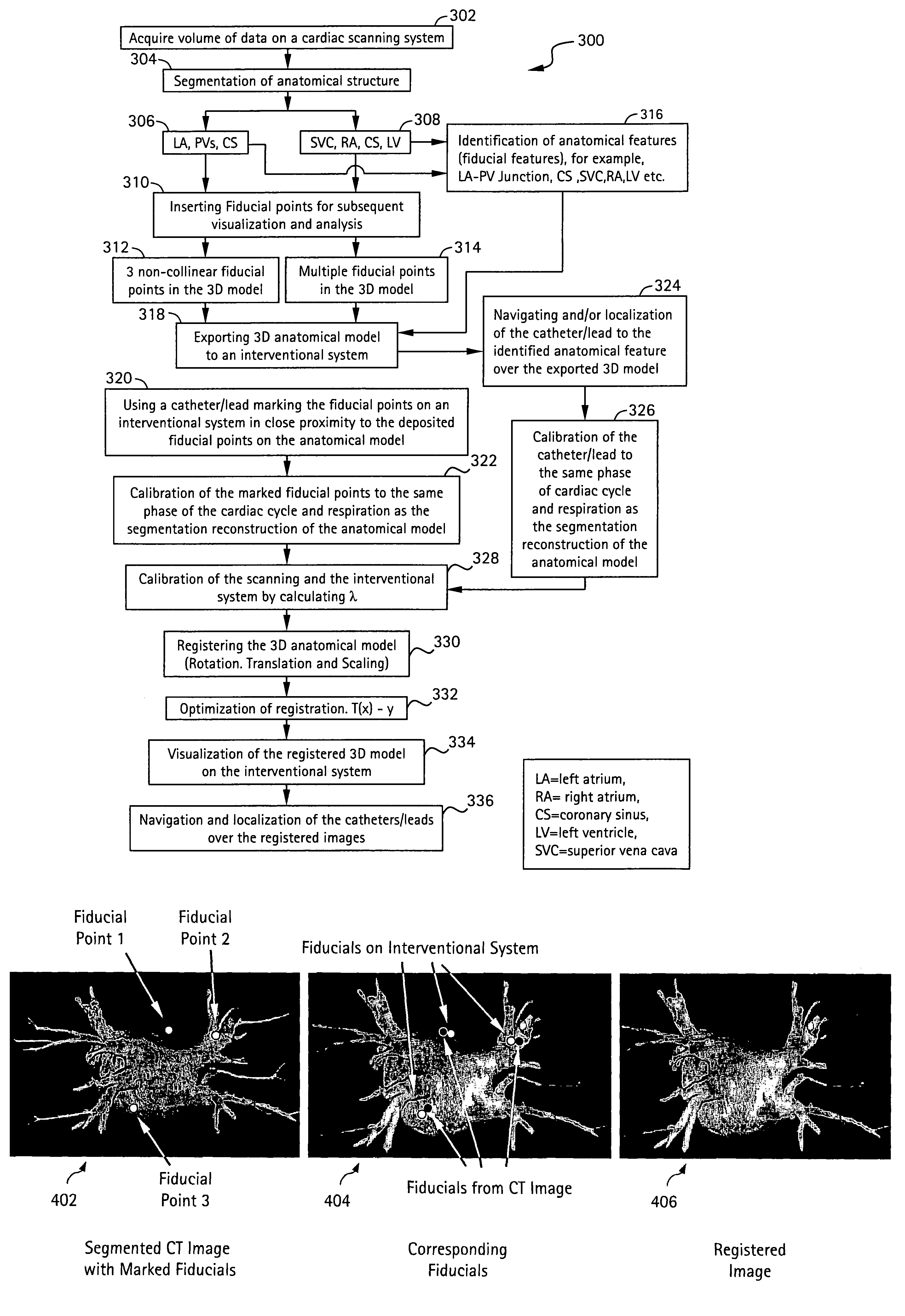
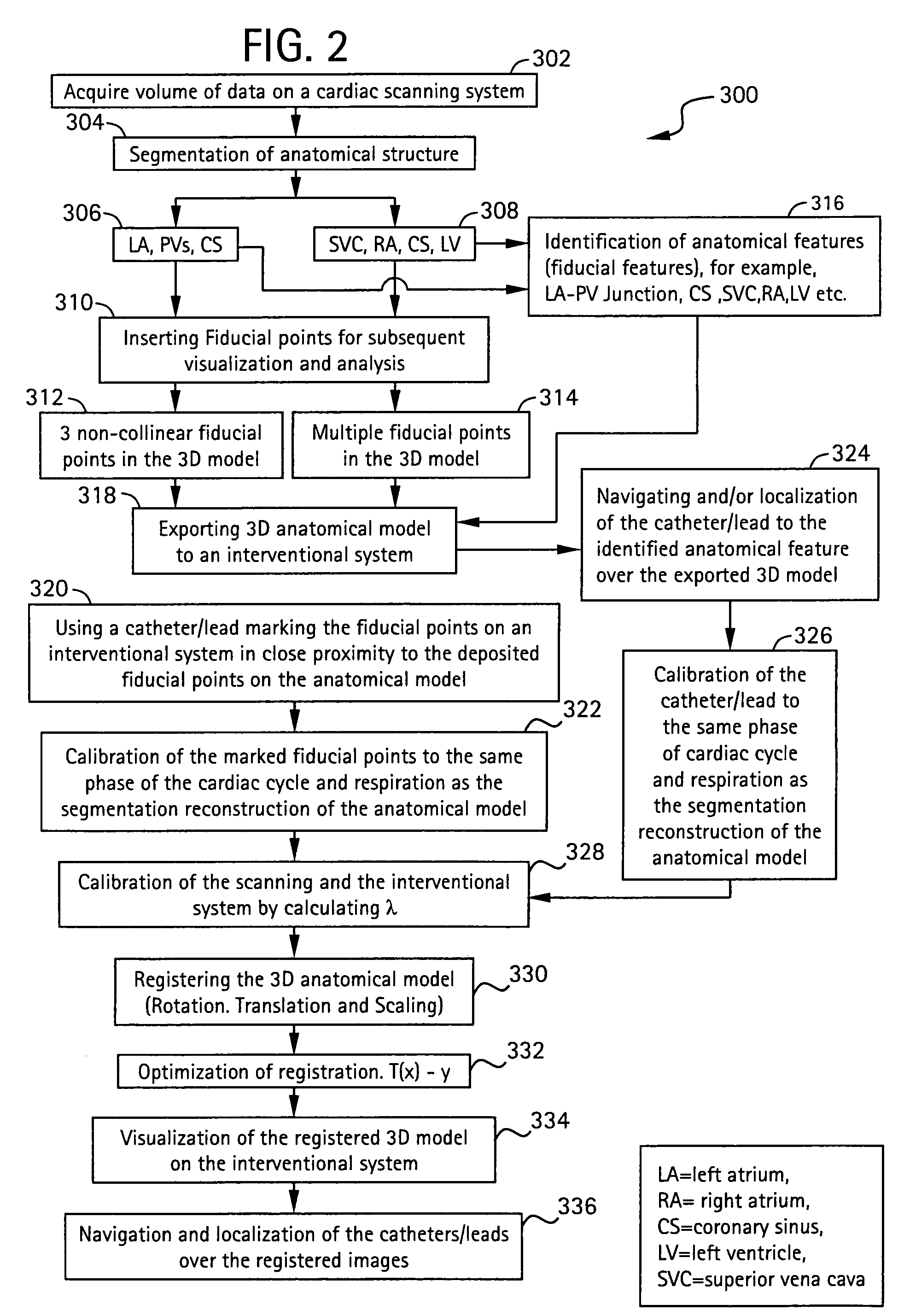
[0033]Disclosed herein is a method and system for registration of anatomical images within an interventional system, in which imported, segmented images (in the form of a 3D model) are registered with an interventional system through the use of deposited fiducial points on the 3D model and / or the navigation and localization of an instrument (e.g., catheter, pacing lead) with respect to one or more identified anatomical features (e.g., the left atrium / pulmonary vein junction of the heart, the coronary sinus, superior vena cava (SVC), etc.). Moreover, the present invention embodiments provide for improved reduction of motion artifacts due to cardiac and respiratory motion by image segmentation, fiducial point deposition and instrument location at about the same phase of the cardiac cycle for example about 75% of the R-R cycle during sinus rhythm, and about 45% to 50% of the R-R interval during atrial fibrillation which can cause fast and irregular R-R intervals. Although the exemplary...


PUM


Abstract

A method for registration of cardiac image data in an interventional system includes inserting a first plurality of fiducial points on an acquired 3D anatomical image and exporting the 3D anatomical image, with the first plurality of inserted fiducial points thereon, to an interventional system. A second plurality of fiducial points is inserted on the exported 3D anatomical image using the interventional system, and the first and said second plurality of fiducial points are aligned to one another so as to register the exported 3D anatomical image with the interventional system.

Description

CROSS REFERENCE TO RELATED APPLICATIONS[0001]This application is a continuation-in-part of U.S. application Ser. No. 10 / 063,064, filed Mar. 15, 2002, the contents of which are incorporated by reference herein in their entirety.[0002]This application is also a continuation-in-part of U.S. application Ser. No. 10 / 065,595, filed Nov. 1, 2002, the contents of which are incorporated by reference herein in their entirety.[0003]This application is also a continuation-in-part of U.S. application Ser. No. 10 / 249,815, filed May 9, 2003, the contents of which are incorporated by reference herein in their entry.[0004]This application also claims the benefit of U.S. provisional application No. 60 / 531,293, filed Dec. 19, 2003, the contents of which are incorporated by reference herein in their entirety.[0005]This application further claims the benefit of U.S. provisional application No. 60 / 531,294, filed Dec. 19, 2003, the contents of which are incorporated by reference herein in their entirety.B...

Claims


Application Information

Patent Timeline
Patent Type & Authority Patents(United States)
IPC IPC(8): A61B5/05G06T7/00
CPCG06T7/0028G06T2207/30048G06T7/33
Inventor VASS, MELISSASRA, JASBIR S.OKERLUND, DARIN R.
Owner APN HEALTH
Why Eureka
Try Eureka