Acoustic wave array chemical and biological sensor

a technology of acoustic wave array and chemical and biological sensors, which is applied in the direction of instruments, specific gravity measurement, furnaces, etc., can solve the problems of large attenuation of rayleigh wave, wave energy leakage into liquid, and difficulty in creating a physical interface between fluids and stw devices

Active Publication Date: 2009-03-10
SENSANNA
View PDF11 Cites 35 Cited by
  • Summary
  • Abstract
  • Description
  • Claims
  • Application Information

AI Technical Summary

Benefits of technology

[0013]Unlike prior individual and array acoustic wave sensors, the sensor array devices according to one embodiment of the invention require no protective coating over electrode regions, and can be manufactured and assembled using standard flip chip assembly and standard ceramic surface mount packaging techniques. Also unlike prior array acoustic wave sensors, the devices according to an embodiment of the invention can use utilize frequency diversity among channels or coding of individual channels to effect identification of individual sensor channel response. Additionally, sensor array devices according to an embodiment of the invention can utilize proper functionalization of the multiple channels together with channel identification to produce simultaneous measurements of multiple parameters. This can be useful when measuring multiple physical parameters, or when analyzing fluids (liquids and vapors) to determine the presence, absence, or concentration of a specific chemical or biological component. Also unlike prior acoustic wave array devices, the LG-SH-APM array devices according to an embodiment of the invention utilize the highly sensitive layer guided shear horizontal acoustic plate mode wave propagation mode, which when properly designed can produce sensor sensitivities more than an order of magnitude greater than those of conventional SH-APM devices and other acoustic wave sensors.DETAILED DESCRIPTION OF THE PREFERRED EMBODIMENTS
[0024]Finally, sensor embodiments of the current invention utilize guiding layers placed on the substrate surface opposite the surface where the electrodes are located, and sensing occurs on the side of the sensor array containing these guiding layers. Hence, sensor arrays according to the present invention can be packaged using standard SAW device flip chip assembly procedures and standard ceramic surface mount packages. This embodiment of the current invention overcomes the limitations of the prior art, wherein protective layers were required over the transducer regions. No such layers are needed in array sensors according to the present invention. The integrated microfluidic channels of the present invention, taken together with the ease of production and packaging considerations, produce an array sensor that can be manufactured in a cost effective fashion, making truly disposable array sensors feasible. This is a significant advantage, particularly for the point-of-care clinical diagnostic applications such as the STD chip mentioned previously.

Problems solved by technology

When used in a liquid, this component generates a compressional wave in the liquid, causing wave energy to leak into the liquid.
This energy leakage results in large attenuation of the Rayleigh wave, often referred to as “damping”.
This effect makes Rayleigh waves useful only for gas phase sensing, and not applicable to sensing in the liquid phase.
STW devices have the practical drawback of difficulty of creating a physical interface between the fluid (liquid or gas) sample chamber and the active device surface.
To date, the ability to incorporate unique sensor identification and the potential wireless operation aspect of these sensors has not been exploited for chemical and biological sensing applications in vapors and liquids.

Method used


Image

  • Acoustic wave array chemical and biological sensor
  • Acoustic wave array chemical and biological sensor
  • Acoustic wave array chemical and biological sensor

Examples


Embodiment Construction

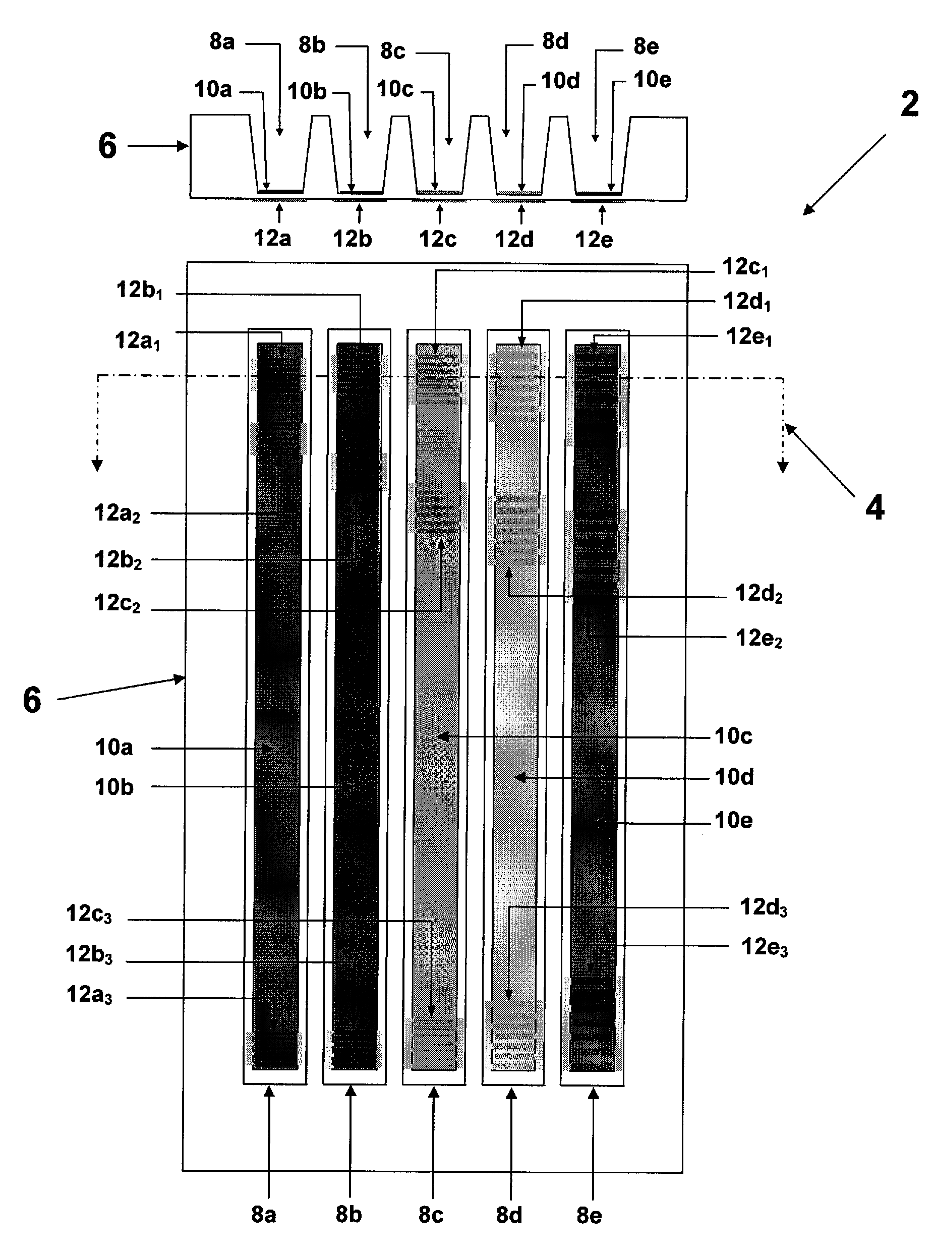
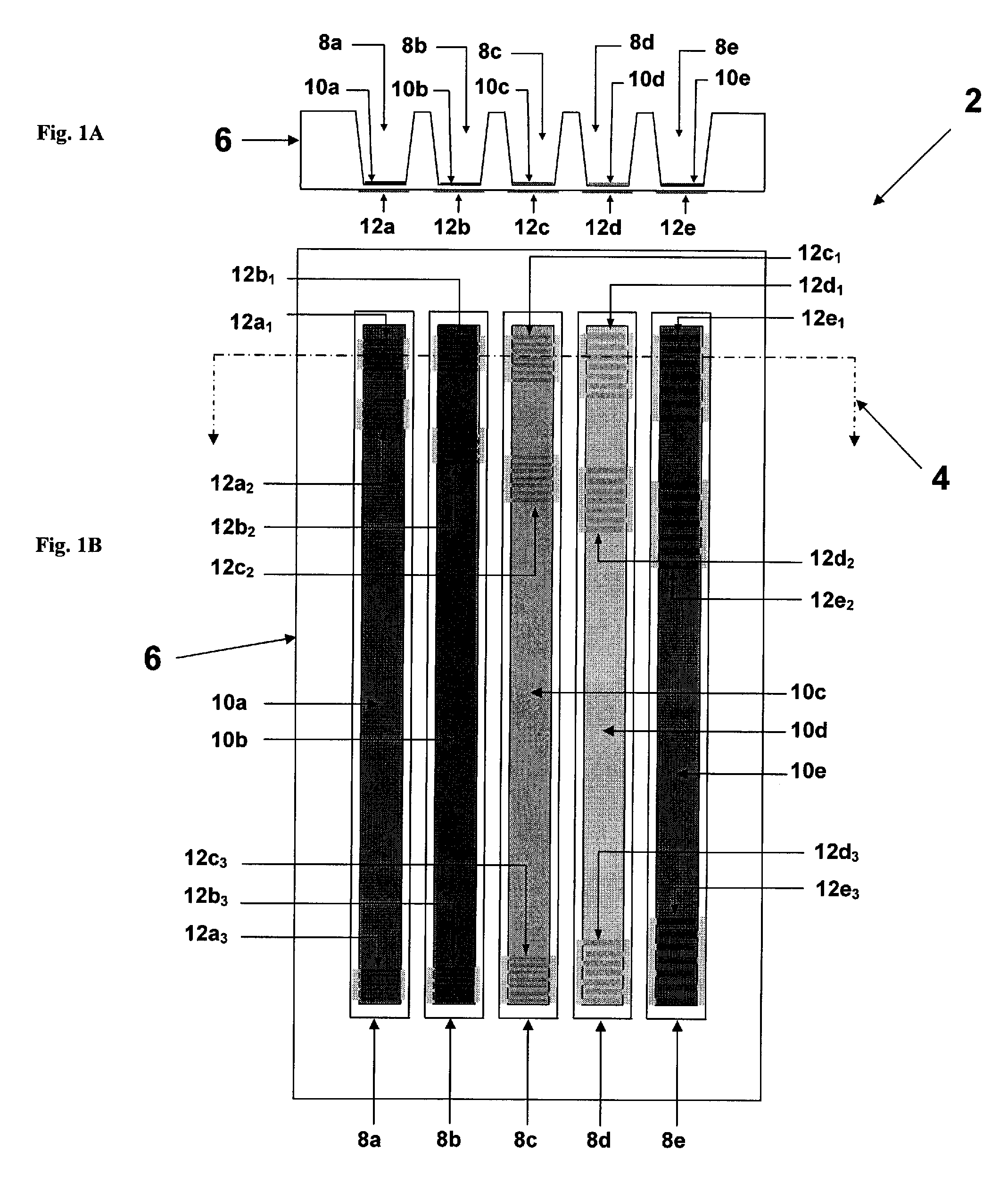
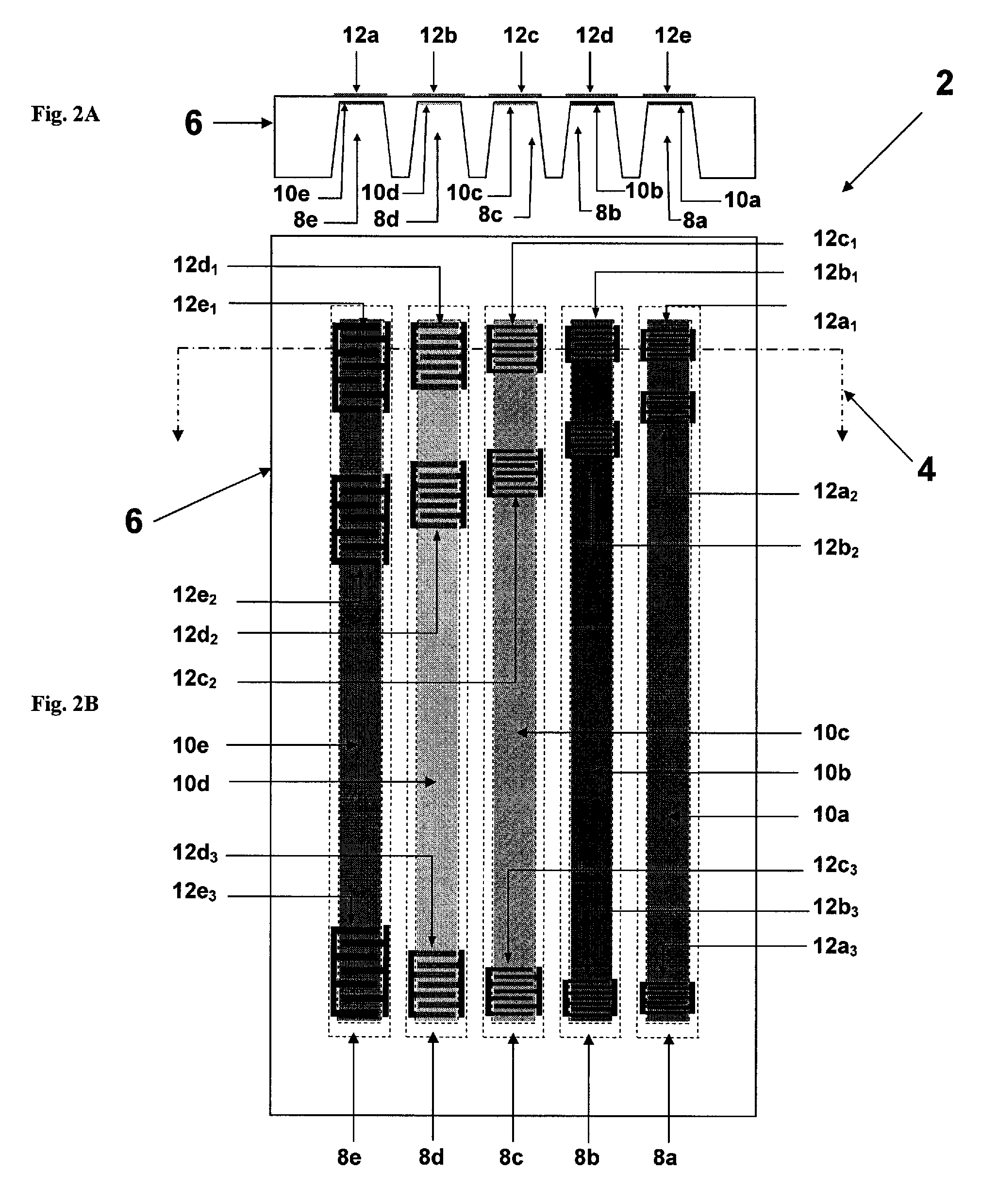
[0014]The acoustic wave array sensors of embodiments of the current invention utilize four fundamentally different elements to realize advantages over prior art acoustic wave sensor array techniques. First, sensor embodiments utilize layer guided shear horizontal acoustic plate mode (LG-SH-APM) waves and associated Love waves propagating in thin-layer single crystal piezoelectric substrates coated with guiding layers to achieve enhanced sensor sensitivity. Multiple integrated microfluidic channels are utilized for ease of manufacturing and sample handling. Second, sensor embodiments utilize frequency diversity among channels or coding of individual channels to effect identification of individual sensor channel responses. Third, functionalization of separate channels is used together with channel identification, to produce simultaneous measurements of multiple parameters. Fourth, sensor embodiments utilize guiding layers placed on the substrate surface opposite the surface where the ...


PUM

PropertyMeasurementUnit
thicknessaaaaaaaaaa
thicknessaaaaaaaaaa
thicknessaaaaaaaaaa

Abstract

An acoustic wave sensor array device is provided for the detection, identification, and quantification of chemicals and biological elements dispersed in fluids. The sensor array device is capable of the simultaneous characterization of a fluid for multiple analytes of interest. A substrate has a plurality of channels formed therein and a sensor material layer applied in a bottom of the channels. The sensor material layer has a shear acoustic wave speed lower than a shear acoustic wave speed in said substrate. The channels may have the same material in each channel or different materials in at least two of the channels. A surface acoustic wave transducer and at least one surface acoustic wave reflector, or at least two transducers is formed on a surface of the substrate opposite the channels at a portion of the substrate that is thinned by the channels, so that the acoustic tracks of the surface acoustic wave device extend along the channels. The response of the surface acoustic wave depends on the response of the sensor material to a sensed fluid supplied to the channels.

Description

CROSS REFERENCE TO RELATED APPLICATION[0001]This application claims the benefit U.S. provisional application No. 60 / 816,464 filed on Jun. 26, 2006, which is incorporated by reference hereinFIELD OF THE INVENTION[0002]The present invention relates generally to a sensor using surface acoustic wave technology and in particular to apparatus, systems, devices, and methods using at least one and preferably multiple acoustic tracks for sensing chemical and biological agents using surface acoustic wave sensors.BACKGROUND AND BRIEF DESCRIPTION OF THE RELATED ART[0003]Sensors based on surface-launched acoustic wave devices have been developed since the 1980's for application to physical measurements (temperature, pressure, torque, strain, etc.) and to a wide range of chemical and biological detection problems. These widely varying devices have utilized several operating modes and corresponding wave propagation modes, including the traditional Rayleigh wave (or Surface Acoustic Wave—SAW), the ...

Claims


Application Information

Patent Timeline
Patent Type & Authority Patents(United States)
IPC IPC(8): G01N29/036H01L41/08
CPCG01N29/022G01N29/222G01N29/2481G01N2291/0255G01N2291/0256G01N2291/0423G01N2291/106
Inventor HINES, JACQUELINE H.
Owner SENSANNA
Why Eureka
Try Eureka