
Kerogen extraction from subterranean oil shale resources

a technology of oil shale resources and kerogen, which is applied in the direction of survey, insulation, borehole/well accessories, etc., can solve the problems of long timeframe, unreliable oil recovery, and high energy consumption in the world, and achieves the effect of reducing the cost of shell approach, and increasing the cost of oil shale recovery

Inactive Publication Date: 2009-03-10
CHEVROU USA INC +1
View PDF23 Cites 50 Cited by
  • Summary
  • Abstract
  • Description
  • Claims
  • Application Information

AI Technical Summary

Benefits of technology

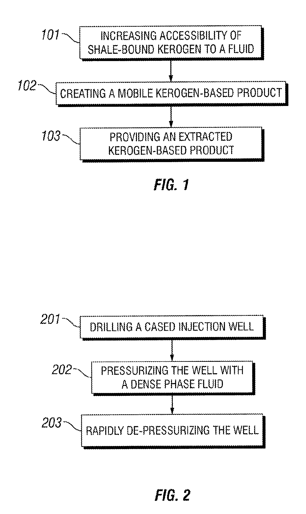
[0013]In some embodiments, the present invention is directed to methods for extracting a kerogen-based product from a subsurface shale formation comprising subsurface shale, the methods comprising the steps of: (a) increasing accessibility of kerogen in subsurface shale to a fluid, wherein the subsurface shale comprises an inorganic component in addition to the kerogen; (b) contacting the kerogen in the subsurface shale with an extraction fluid to create a mobile kerogen-based product; and (c) transporting the mobile kerogen-based product out of the subsurface shale formation to yield an extracted kerogen-based product.
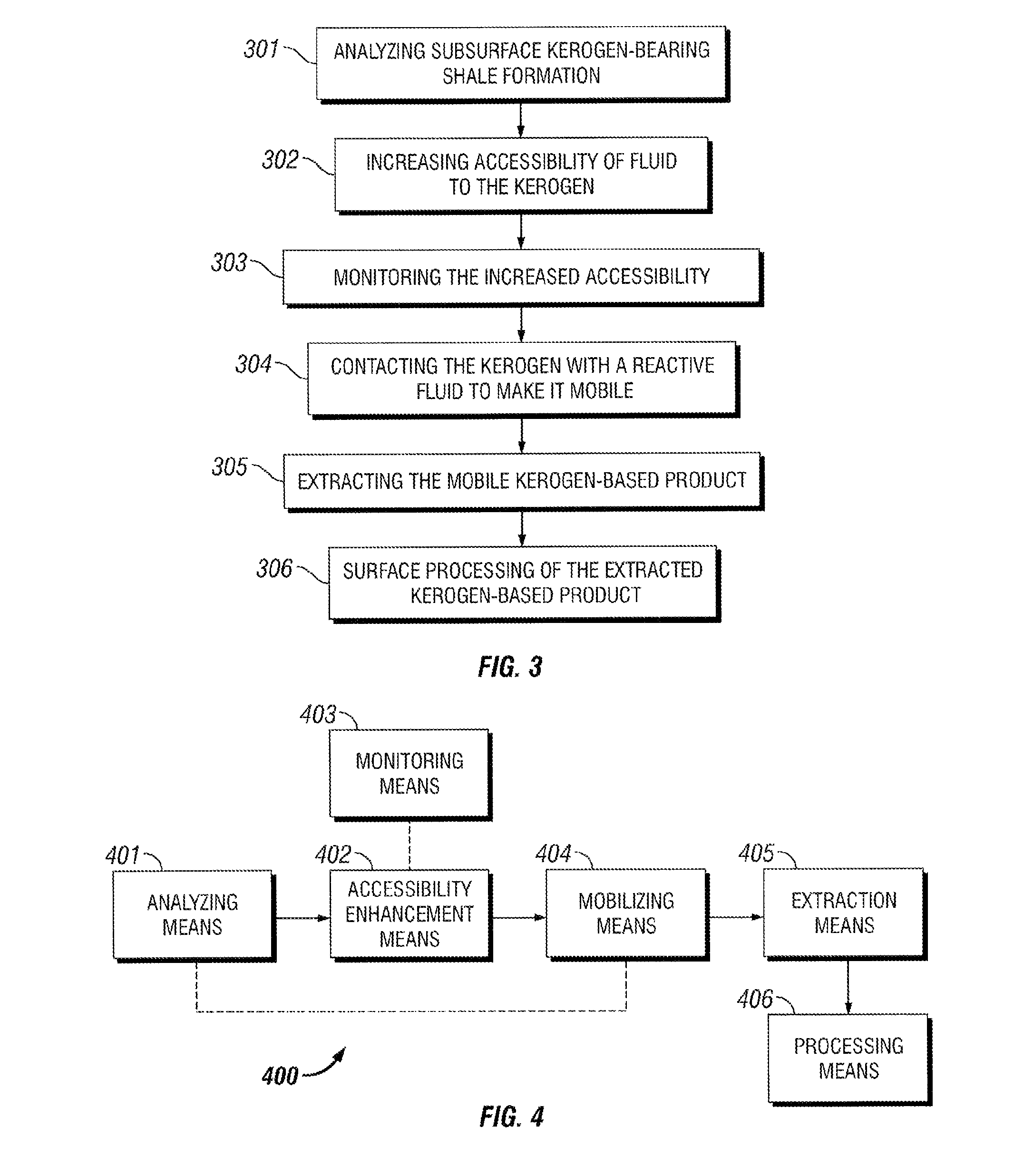
[0017]In some embodiments, the present invention is directed to methods comprising the steps of: (a) analyzing a subsurface kerogen-bearing shale formation so as to derive information regarding the kerogen contained therein; (b) increasing accessibility of said kerogen in the subsurface shale to a fluid, wherein the subsurface shale comprises an inorganic component in addition to the kerogen; (c) monitoring the increased accessibility provided in step (b); (d) contacting the kerogen in the subsurface shale with a reactive fluid to create a mobile kerogen-based product, wherein said reactive fluid is selected in view of the information derived in step (a); and (e) transporting the mobile kerogen-based product out of the subsurface shale formation to yield an extracted kerogen-based product. Optionally, such methods can further comprise a step of processing the extracted kerogen-based product.

Problems solved by technology

Regardless, world energy consumption continues to rise at a rate that outpaces new oil discoveries.
While the establishment of “freeze walls” is an accepted practice in civil engineering, its application to oil shale recovery still has unknown environmental impacts.
Additionally, the Shell approach is recognized as an energy intensive process and requires a long timeframe to establish production from the oil shale.

Method used


Image

  • Kerogen extraction from subterranean oil shale resources
  • Kerogen extraction from subterranean oil shale resources
  • Kerogen extraction from subterranean oil shale resources

Examples


example 1

[0069]This Example serves to illustrate how shale in a subsurface formation can be sampled and analyzed prior to fracturing and / or rubblizing, in accordance with some embodiments of the present invention.

[0070]Whole or conventional cores can be obtained using standard core sampling techniques known in the art and using bits such as Baker Hughes INTEQ coring bits. Sidewall and sidewall rotary cores can also be obtained, but these are typically smaller and generally of lower quality. Once obtained, the core samples can be subjected to a variety of analyses including, but not limited to, core gamma analysis, density, circumferential imaging and computed tomography (CT) scanning, fracture analysis, permeability, porosity, hydrocarbon recovery when exposed to the reactive fluid, electrical measurements, thermal conductivity measurements, rock mechanics, X-ray diffraction (XRD), nuclear magnetic resonance (NMR), total organic carbon (TOC), fluorescence and / or infrared spectroscopy, etc.

[0...

example 2

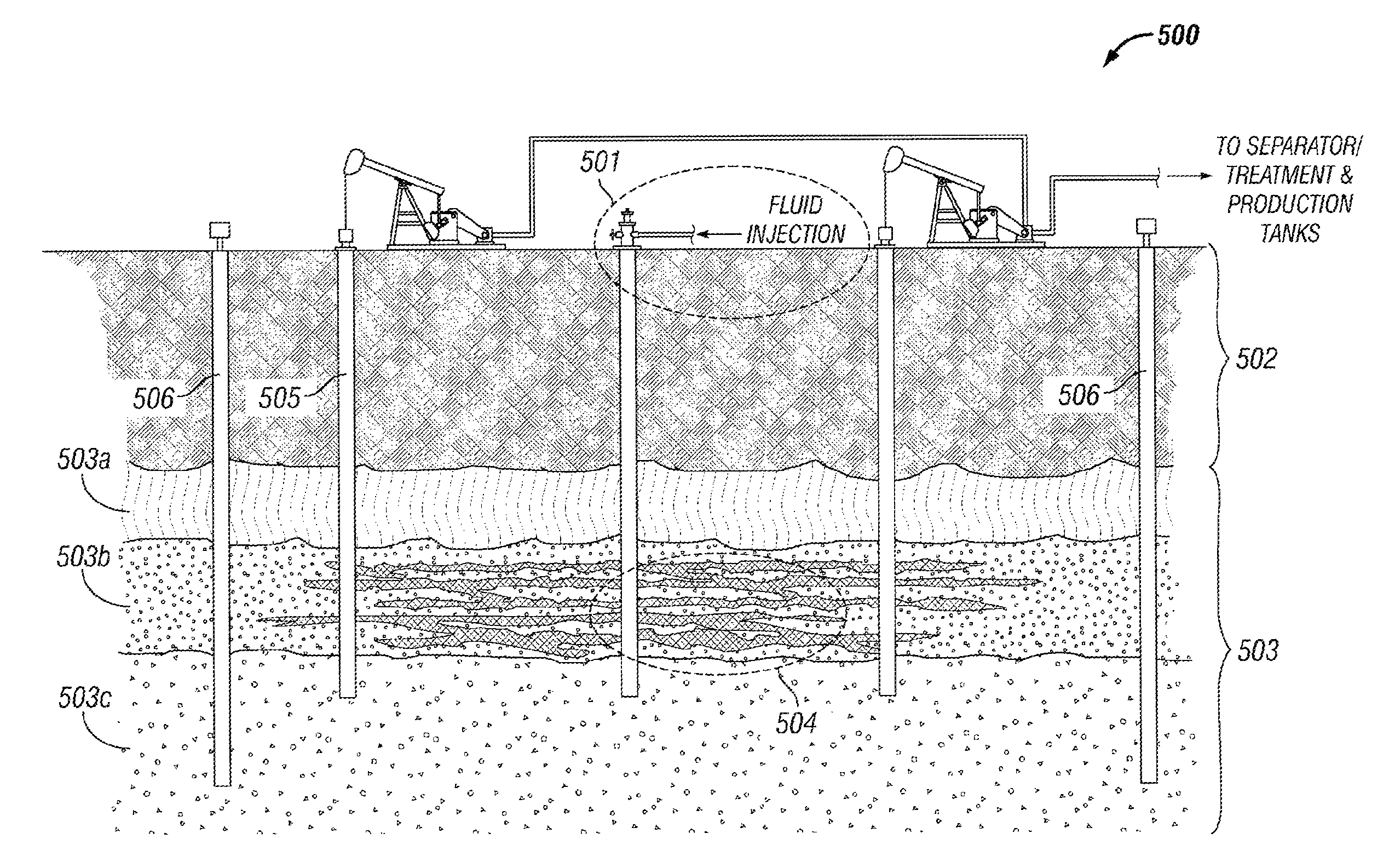
[0073]This Example serves to illustrate fracturing and / or rubblizing of shale in a subsurface shale formation so as to increase fluid accessibility to the kerogen contained therein, in accordance with some embodiments of the present invention, and particularly within the context of the exemplary system embodiment depicted in FIG. 5.

[0074]Referring to FIG. 5, integrated system 500 comprises establishing an injection well 501 that extends into the subsurface through the (e.g., Uinta) formation 502 and the (e.g., Green River) formation 503, wherein the latter is subdivided into three zones (503a, 503b, and 503c). Fluids are injected into the formation via injection well 501 and provide a fractured formation 503b having increased fluid accessibility to the kerogen contained therein. Such fluid access further provides for contacting the kerogen with a reactive fluid and extraction fluid so as to extract the mobile kerogen-based product out of the formation via one or more producing wells...

example 3

[0075]This Example serves to illustrate how the fracturing and / or rubblizing of shale in a subsurface shale formation can be monitored, in accordance with some embodiments of the present invention.

[0076]In lieu of, or in addition to, the groundwater monitoring well(s) described in Example 2, tiltmeters can be installed in a patterned arrangement on the surface of the shale formation. The tiltmeter installations would be in 8.5 inch holes, 25 feet deep, and lined with PVC pipe and perhaps a little cement on the bottom. They would be capped and have a solar panel for data collection. Geophones can also be installed either at the surface or sub-surface to gather micro-seismic information to help track fracture growth.


PUM


Abstract

The present invention is directed to methods for extracting a kerogen-based product from subsurface (oil) shale formations, wherein such methods rely on fracturing and / or rubblizing portions of said formations so as to enhance their fluid permeability, and wherein such methods further rely on chemically modifying the shale-bound kerogen so as to render it mobile. The present invention is also directed at systems for implementing at least some of the foregoing methods. Additionally, the present invention is also directed to methods of fracturing and / or rubblizing subsurface shale formations and to methods of chemically modifying kerogen in situ so as to render it mobile.

Description

CROSS-REFERENCE TO RELATED APPLICATIONS[0001]The present Application for Patent claims priority to the following U.S. Provisional Patent Applications: 60 / 774,337, filed Feb. 16, 2006; and 60 / 846,982, filed Sep. 25, 2006.[0002]This Invention was made with Government support under Contract Number DE-AC51-06NA25396 awarded by the United States Department of Energy. The Government has certain rights in the invention.FIELD OF THE INVENTION[0003]This invention relates to methods of extracting organic molecules from subterranean shale resources containing an organic kerogen component, particularly wherein such methods involve a step of increasing said kerogen component's accessibility to a fluid.BACKGROUND[0004]If proponents of Hubbert peak theory are correct, world oil production will soon peak, if it has not done so already. Regardless, world energy consumption continues to rise at a rate that outpaces new oil discoveries. As a result, alternative sources of energy must be developed, as ...

Claims


Application Information

Patent Timeline
Patent Type & Authority Patents(United States)
IPC IPC(8): E21B43/22E21B43/25E21B43/263E21B49/00
CPCC09K8/594E21B43/241E21B43/247Y02P20/54
Inventor LOONEY, MARK DEANLESTZ, ROBERT STEVENHOLLIS, KIRKTAYLOR, CRAIGKINKEAD, SCOTTWIGAND, MARCUS
Owner CHEVROU USA INC
Learn More