Seat belt device

a seat belt and belt technology, applied in the direction of engine starters, pedestrian/occupant safety arrangements, explosion-based starters, etc., can solve the problems of increased pressure loss, sudden change, and increased pressure loss, and achieve the effect of reducing pressure loss and preventing chang

Active Publication Date: 2009-03-10
NSK AUTOLIV
View PDF19 Cites 9 Cited by
  • Summary
  • Abstract
  • Description
  • Claims
  • Application Information

AI Technical Summary

Benefits of technology

[0015]It is ideal that the venting characteristic is smaller when the pretensioner is activated, while the venting characteristic is greater and smoother at the time of energy absorption.
[0016]Therefore, it is an object of the present invention to provide a seat belt device in which the diameter of a vent hole is made smaller at first to reduce a pressure loss when the pretensioner is activated. Then, the gas is vented gradually and large amount by the diameter of the vent hole is expanded, since a high temperature combustion gas passes through a capillary.

Problems solved by technology

However, with this method, when the blow-by patch is released, the pressure is released literally, causing a sudden change.
However, if the blow-by patch is released, a sudden change occurs.
Also, if the hole diameter is greater not to release the blow-by patch, the venting is increased, producing a greater pressure loss when the pretensioner is activated.

Method used


Image

  • Seat belt device
  • Seat belt device
  • Seat belt device

Examples


first embodiment

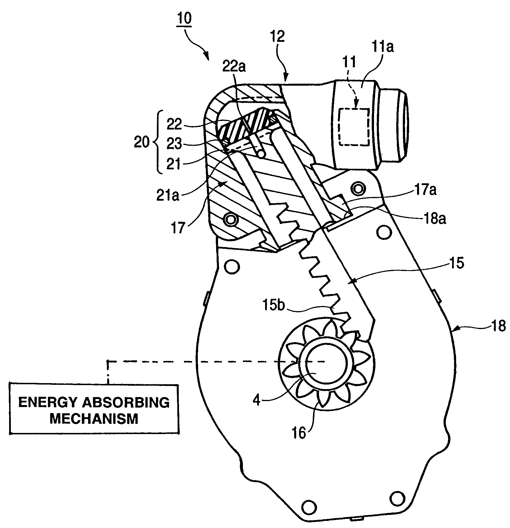
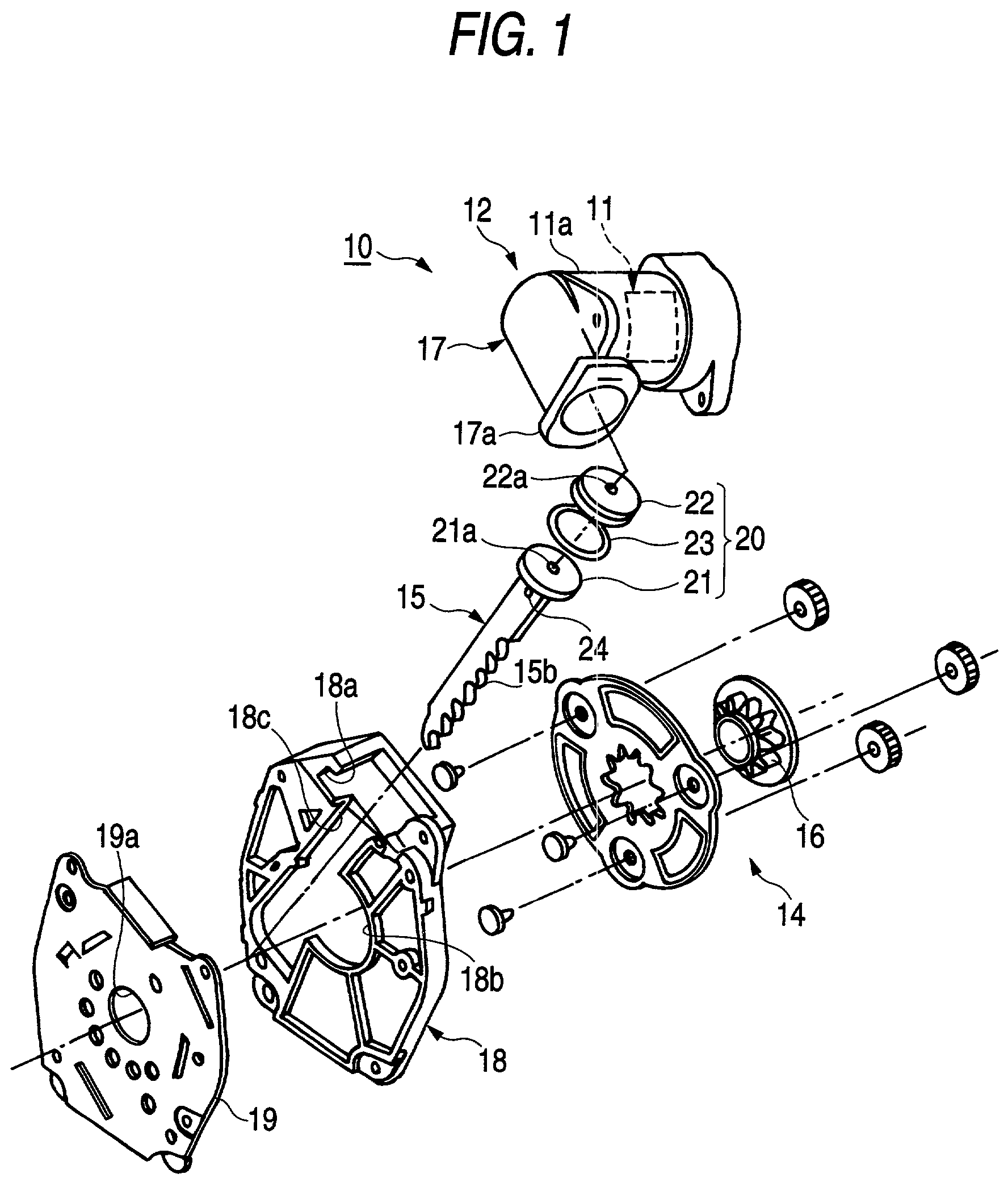
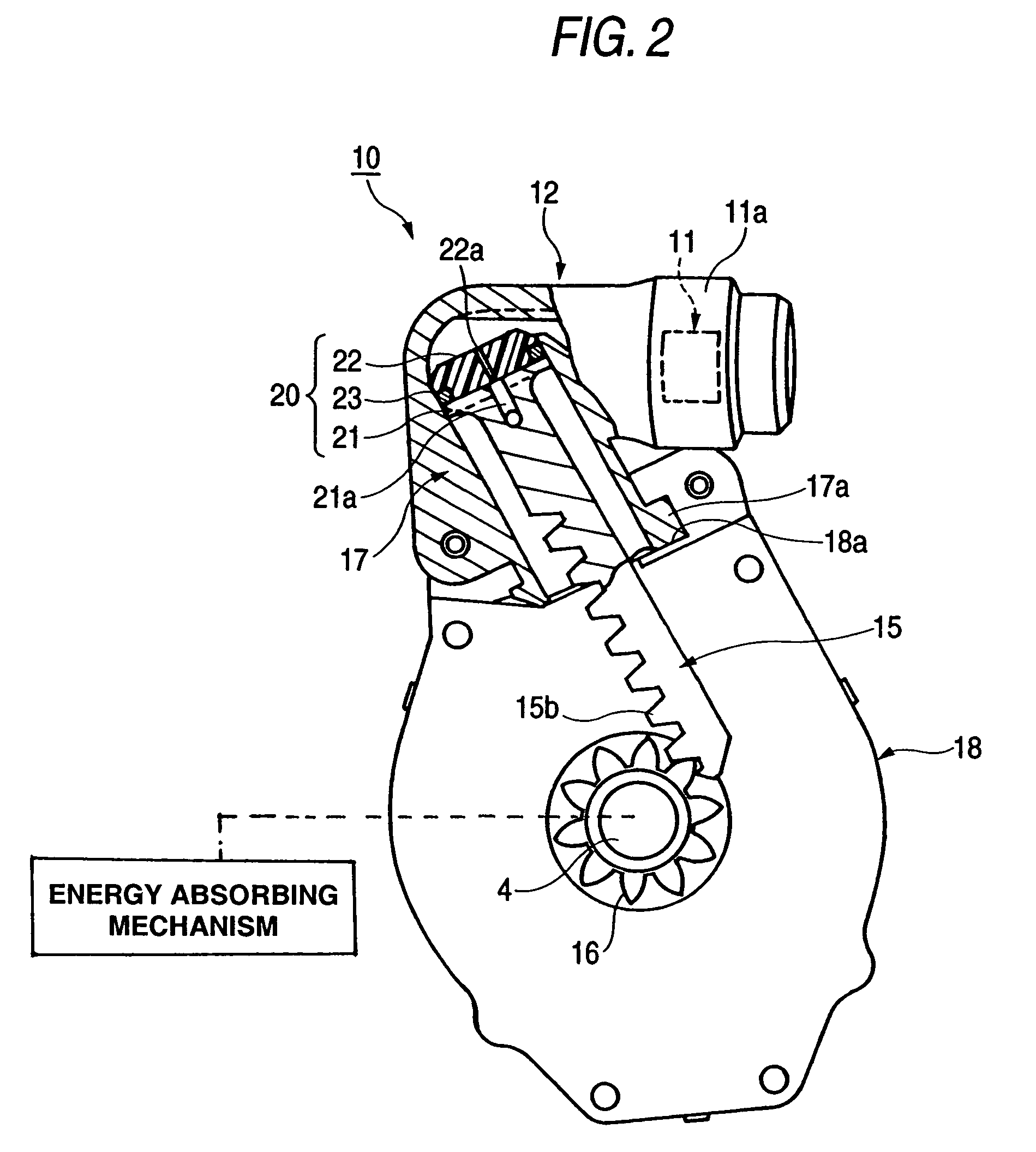
[0033]The preferred embodiments of the present invention will be described below with reference to the accompanying drawings. FIG. 1 is an exploded perspective view of a pretensioner 10 in a seat belt device according to the present invention. FIG. 2 is a cross-sectional view showing an initial state of the pretensioner 10 as shown in FIG. 1.

[0034]This pretensioner 10 is equipped in a seat belt retractor for the vehicle such as a car to remove the slack of a belt (webbing) when the vehicle is emergency such as the time of collision. The pretensioner 10 can transmit a torque via a clutch mechanism, not shown, to a winding shaft 4 (see FIG. 2) of the retractor.

[0035]This pretensioner 10 conducts a high temperature and high pressure gas generated by a gas generator 11 through a gas generator case 11a covering the gas generator 11 to a cylinder 17. The cylinder 17 has one end (base end) connected to the gas generator case 11a, with the other end being connected via a jaw portion 17a pro...

second embodiment

[0057]In this second embodiment, the entire bush 32 that is a deformable member is fitted into a piston main body 31 formed integrally at the base end of the rack 15 that is a non-deformable member. A ring-like seal member 33 is fitted within a concave portion provided on a face of the piston main body 31 opposite to the pressure vessel 12. The bush 32 is formed almost cylindrically, and has a first gas passageway 32a like a capillary passing through its central axis.

[0058]The second gas passageway 31a like a capillary passes penetrates through the center of the cylindrical piston main body 31 which has a bottom. The first gas passageway 32a and the second gas passageway 31a extend on the same straight line, and penetrate the piston 30. In an initial state, the first gas passageway 32a is slender than the second gas passageway 31a, and, for example, is a capillary having the same diameter of the first embodiment.

[0059]The second gas passageway 31a extends into the rack 15, and is in...

third embodiment

[0061]FIG. 6 is a cross-sectional view showing the relevant part of a pretensioner in a seat belt: device according to the present invention.

[0062]In this third embodiment, the entire bush 42 that is a deformable member is fitted into a piston main body 41 formed integrally at the base end of the rack 15 that is a non-deformable member. A ring-like seal member 43 is fitted within a concave portion provided on a face of the piston main body 41 opposite to the pressure vessel 12.

[0063]The bush 42 is formed almost cylindrically, and has a first gas passageway 42a like a capillary passing through its central axis. Further, the bush 42 has a lightening hole 42b as an auxiliary space formed at an interval radially from the first gas passageway 42a. A plurality of lightening holes 42b maybe provided at regular intervals circumferentially, or like a ring. In this embodiment, the lightening hole 42b is in communication with none of the first gas passageway 42a, the second gas passageway 41a,...


PUM


Abstract

A seat belt device has a gas generator for generating a high pressure gas when the vehicle is in emergency, a cylinder for conducting the high pressure gas from the gas generator, a piston received movably within the cylinder and pressed and moved by the high pressure gas, and a drive unit for rotating a winding shaft of a seat belt retractor in a direction of removing the slack of a belt, using the movement of the piston, wherein the pretensioner is employed with the energy absorbing mechanism, for reversely rotating the winding shaft if a tension acting on the belt exceeds a predetermined value after removing the slack of the belt.

Description

BACKGROUND OF THE INVENTION[0001]The present invention relates to a seat belt device having a retractor, and more particularly to a seat belt device equipped with a pretensioner for rotating a winding shaft of the retractor in a direction of removing a slack of the belt.[0002]Conventionally, some retractors for the seat belt device can remove the slack of the belt (webbing) by means of the pretensioner, when the vehicle is in emergency such as collision. Also, other retractors have an energy absorbing mechanism for absorbing an impact on the body of the crew by letting out a predetermined amount of the belt, when a load acting on the belt exceeds a predetermined value after removing the slack of the belt by the pretensioner.[0003]In JP-A-9-188223, a linear drive device (pretensioner) was disclosed, comprising a cylindrical tube, a piston having a hollow inner space and an end wall at one end portion in an axial direction to be slidable within the cylindrical tube, and a charge for s...

Claims


Application Information

Patent Timeline
Patent Type & Authority Patents(United States)
IPC IPC(8): B60R22/46B60R21/26
CPCB60R22/4633B60R2022/4661
Inventor ONO, KATSUYASUOHSUMI, SADANORIMATSUKI, MASUOOGAWA, KIYOSHI
Owner NSK AUTOLIV
Why Eureka
Try Eureka