Insert with replaceable cutting edge and corner milling cutter with replaceable cutting edge

a technology of inserting and cutting edge, which is applied in the field of inserting corner milling cutter with replaceable cutting edge, can solve the problems of reducing the cutting quality of the insert, and the method, however, cannot overcome the problems described, and achieves the effect of increasing economic advantages

Active Publication Date: 2009-03-10
SUMITOMO ELECTRIC HARDMETAL CORP
View PDF12 Cites 2 Cited by
  • Summary
  • Abstract
  • Description
  • Claims
  • Application Information

AI Technical Summary

Benefits of technology

[0011]The object of the present invention is to improve the shape of an insert with replaceable cutting edge in order to improve the squareness of the corner and the flatness of the cut wall surface of a workpiece cut with a corner milling cutter that uses this insert.
[0015]When the twisted surface described above is formed from a section of the third surface serving as the outer perimeter flank face, the ridge line formed between the first surface serving as the rake face and the twisted surface (the ridge line serving as the main cutting section) is shaped so that it is expanded outward around an intermediate longitudinal position when the first surface is seen directly from the front. Also, the dulling effect of the twisted surface on the cutting edge increases the strength of the cutting edge.
[0016]When a height offset is provided for the first surface to raise the surface toward the corner, an outer perimeter flank is formed on the third surface and positive angle radial rake γf is applied to the cutting edge, thus improving the cutting quality of the cutting edge. When a height offset is formed on the first surface so that only one set of diagonal corners are raised, the axial rake γp is also set to be positive, providing further improvements in cutting quality. When all four corners of the first surface are raised, it may not be possible to set the axial rake γp to be positive. But even if the axial rake γp has to be negative, the rake angle is larger compared to a structure with no height offset in the first surface, so the cutting quality is improved. When a positive land is formed on the outer perimeter section of the first surface, the cutting edge can be made sharp and the cutting quality can be improved.
[0018]Furthermore, when the corner at which the fifth surface and the third surface intersect has an angle of no more than 95 deg, it is easy to provide a positive face angle (front cutting section angle).
[0019]In addition, with a structure where, when the insert is rotated 180 deg along a horizontal plane, an outline shape stays identical between the third surface and the fourth surface and between the fifth surface and the sixth surface, two diagonal corners or four corners of the first surface can be used as cutting sections. In addition, with a structure where, when the insert is flipped around a bisecting line (L) bisecting a height axis of the first surface, an outline shape stays identical between the first surface and the second surface, two diagonal corners or four corners can be used as cutting sections, thus increasing economic advantages.

Problems solved by technology

A negative radial rake, however, reduces the cutting quality of the cutter.
This method, however, cannot overcome the problems described above.

Method used


Image

  • Insert with replaceable cutting edge and corner milling cutter with replaceable cutting edge
  • Insert with replaceable cutting edge and corner milling cutter with replaceable cutting edge
  • Insert with replaceable cutting edge and corner milling cutter with replaceable cutting edge

Examples


Embodiment Construction

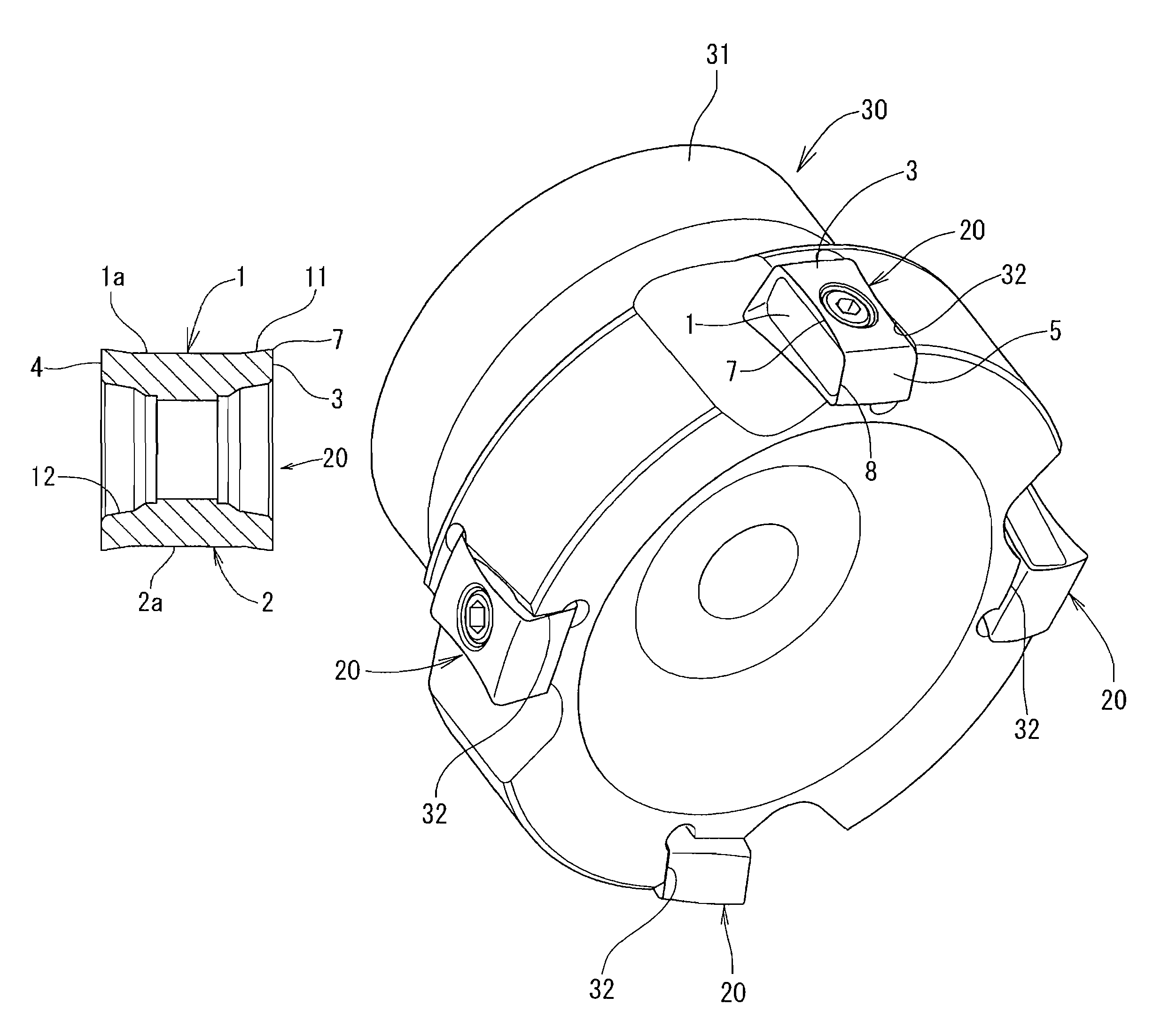
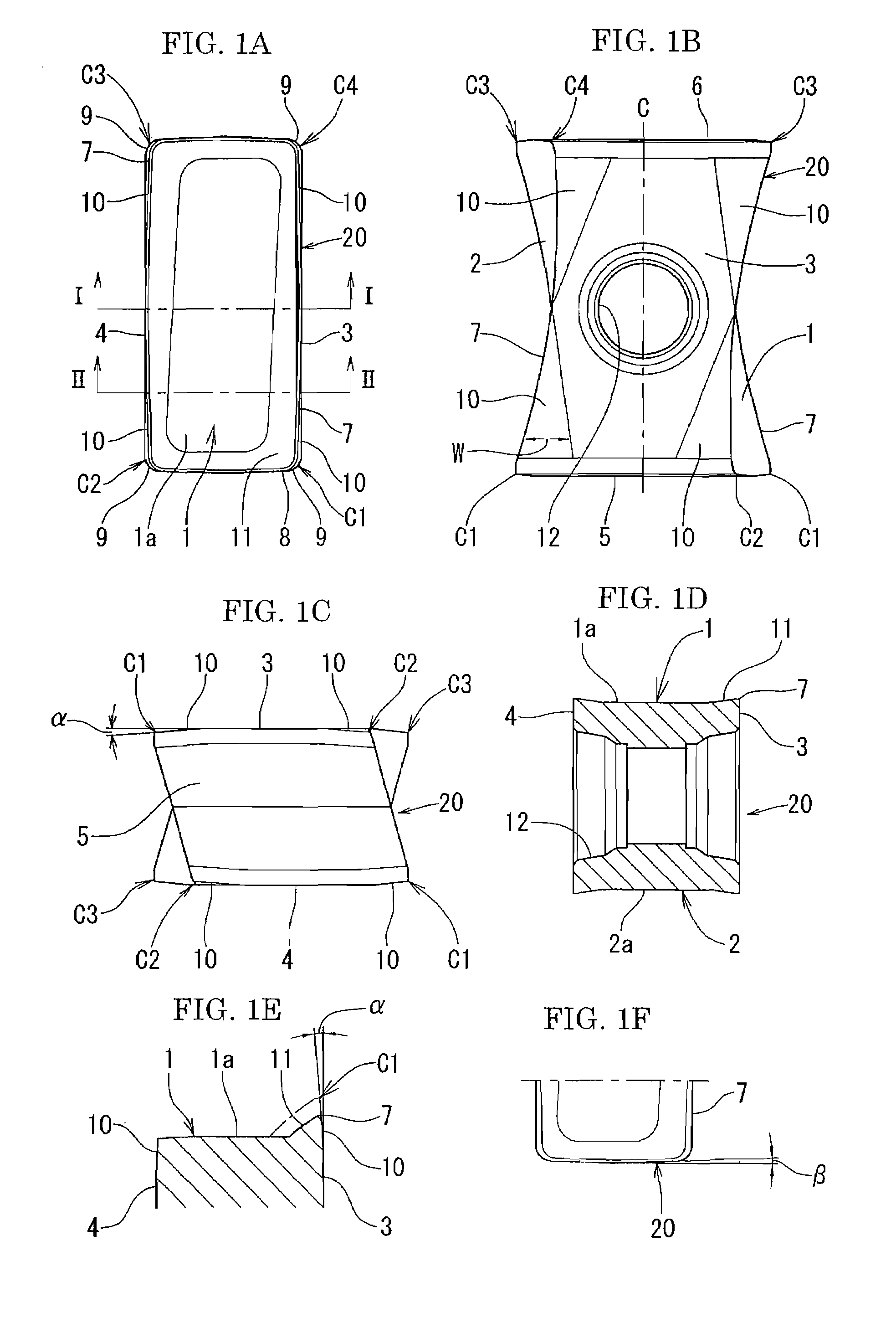
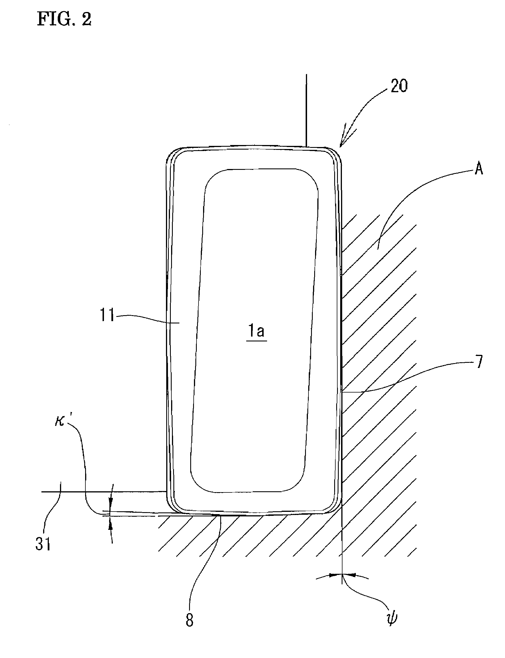
[0032]FIG. 1 through FIG. 5 show a specific example of an insert with replaceable cutting edge according to the present invention. In FIG. 1, a replaceable cutting edge insert 20 is formed as an insert with: a long first surface 1 and a second surface 2 facing in opposite directions; a third surface 3 and a fourth surface 4 intersecting with and connected to a first side edge and a second side edge of the first surface 1 and the second surface 2; and a fifth surface 5 and a sixth surface 6 intersecting with and connected to a first end and a second end of the first surface 1 and the second surface 2. The fifth surface 5 and the sixth surface 6 are also connected, by way of corner curve surfaces 9 to a first end and a second end of the third surface 3 and the fourth surface 4

[0033]The first surface 1 and the second surface 2 are surfaces formed with the same shape, and these surfaces can be switched to serve as rake faces. Positive lands 11 are formed at the outer perimeters of the f...


PUM

PropertyMeasurementUnit
angleaaaaaaaaaa
approach angleaaaaaaaaaa
angleaaaaaaaaaa

Abstract

A replaceable-blade cutting insert for corner milling cutters has a first and second surface; a third and fourth surface connected to a first side edge and a second side edge thereof respectively; and a fifth and sixth surface connected to a first edge and a second edge of the first surface and the second surface respectively. The first surface is used as rake face, the third surface is used as an outer perimeter flank face, and the fifth surface is used as a forward flank face. A twisted surface is disposed on a section of the third surface, forming a ridge line that acts as a main cutting edge intersecting with the first surface and interposed between the third and first surface. The first and second surface can be positioned with a height offset relative to each other so that at least one set of diagonal corners are projected.

Description

INCORPORATION BY REFERENCE[0001]The present application claims priority under 35 U.S.C. §119 to Japanese Application No. 2005-322115, filed on Nov. 7, 2005. The content of the application is incorporated herein by reference in its entirety.BACKGROUND OF THE INVENTION[0002]1. Field of the Invention[0003]The present invention relates to a insert with a replaceable cutting edge. More specifically, the present invention relates to a replaceable-blade cutting insert and corner milling cutter with replaceable cutting edge using the same, in which the squareness of the cut corner and the flatness of the vertical wall of the cut corner are improved. The corner milling cutter of the present invention also includes end mills with replaceable cutting edges.[0004]2. Description of the Background Art[0005]Among widely known corner milling cutters, there are ones in which a cutting section is formed as an insert with a replaceable cutting edge (Japanese Laid-Open Patent Publication Number 2003-26...

Claims


Application Information

Patent Timeline
Patent Type & Authority Patents(United States)
IPC IPC(8): B23B27/16B23B27/00
CPCB23C5/06B23C5/202B23C2200/083B23C2200/123B23C2200/203B23C2200/205Y10T407/24B23C2210/0435B23C2210/045B23C2200/367Y10T407/245Y10T407/23Y10T407/235B23C2200/286B23C2200/284B23C5/205B23C2200/287
Inventor MAETA, ATSUHIKOEMOTO, SHIGENORI
Owner SUMITOMO ELECTRIC HARDMETAL CORP
Why Eureka
Try Eureka