
Slipping layer for dye-donor element used in thermal dye transfer

a technology of dye-donor elements and thermal dye transfer, which is applied in the direction of thermography, printing, duplicating/marking methods, etc., can solve the problems of contaminated layers producing different colors, affecting the quality of the print, and noticeable staining in the white area of the prin

Inactive Publication Date: 2009-03-10
KODAK ALARIS INC
View PDF30 Cites 36 Cited by
  • Summary
  • Abstract
  • Description
  • Claims
  • Application Information

AI Technical Summary

Benefits of technology

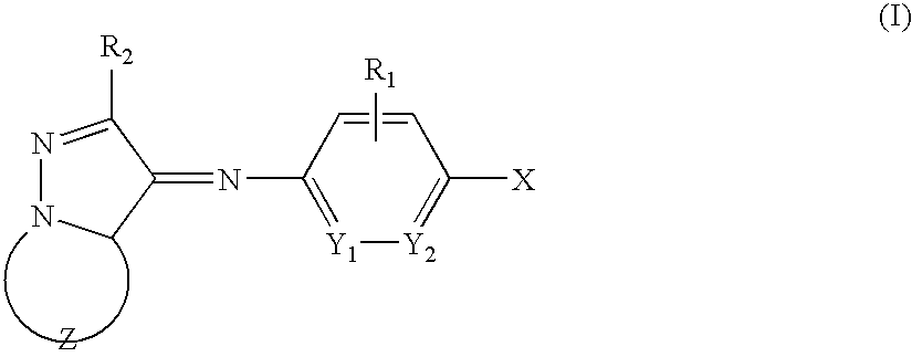
The present invention relates to a dye-donor element for thermal dye transfer with reduced 2× retransfer. The dye-donor element comprises a support with a dye layer on one side and a slipping layer on the other side. The slipping layer comprises a first wax and at least one other wax. The dye layer comprises at least a magenta dye of the structure I described above. The dye-donor element has improved properties such as reduced 2× retransfer and improved color reproduction.

Problems solved by technology

Such higher dye / binder ratios can, however, lead to quality problems following the manufacture of the dye transfer ribbons.
This problem can occur in the manufacturing operation but is exacerbated under the conditions of high temperature and humidity that may occur sporadically in long-distance shipping operations.
At the time of printing onto an image receiving sheet, such contaminated layers produce colors which are different from those intended.
Most objectionable is the noticeable stain in white areas of the print associated with undesirable dye transfer from the clear protective patch.
Such increased surface roughness can lead to print head abrasion problems.
JP02069292 proposes the use of a specific cyan dye to reduce retransfer but such dyes are not optimum in other respects.
Up till now, satisfactory retransfer properties combined with high speed printing of dyes showing excellent color reproduction and image stability have not been achieved.

Method used


Image

  • Slipping layer for dye-donor element used in thermal dye transfer
  • Slipping layer for dye-donor element used in thermal dye transfer
  • Slipping layer for dye-donor element used in thermal dye transfer

Examples


donor example 1

Dye Donor Example 1

[0150]Dye donor element 1 was prepared by coating the following layers in the order recited on 4.5 micron poly(ethylene terephthalate) support:[0151](1) a subbing layer of a titanium alkoxide (DuPont Tyzor TBT®) (0.12 g / m2) from n-propyl acetate and n-butyl alcohol solvent mixture, and[0152](2) a dye layer containing the magenta Dye 1 (0.17 g / m2), 2 micron di-vinyl benzene beads (0.004 g / m2), Paraplex G25 from C.P. Hall Co. Chicago, Ill., USA (0.05 g / m2) in a cellulose acetate propionate (CAP) binder (Eastman Chemical Type 482-20) (0.25 g / m2) coated from a toluene, methanol and cyclopentanone solvent mixture.

donor example 2

Dye Donor Example 2

[0153]Dye Donor Element 2 was prepared in the same manner except that magenta Dye 1 was replaced by magenta Dye 2 at 0.17 g / m2.

donor examples 3-5

Dye Donor Examples 3-5

[0154]Dye Donor Elements 3-5 were prepared in the same manner as Example 1, except that magenta dye 1 was replaced by yellow dyes 3, 4, and 5 respectively coated at 0.13 g / m2 with the CAP binder at 0.21 g / m2.


PUM

PropertyMeasurementUnit
melting pointaaaaaaaaaa
softening pointaaaaaaaaaa

Abstract

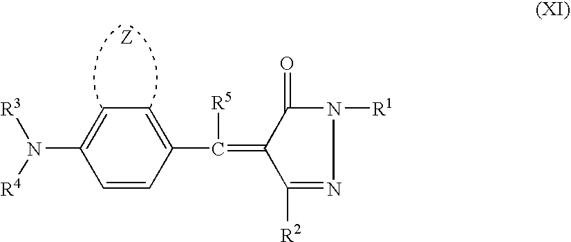
The present invention relates to a dye-donor element for thermal dye transfer comprising a support having on one side a dye layer and on a second side a slipping layer, wherein the slipping layer comprises a first wax comprising a polymer derived from a polyolefin and an ethylenically unsaturated carboxylic acid or ester or anhydride thereof, and at least one other wax and wherein the dye layer comprises at least a magenta dye of the Structure I:wherein the dye donor element has reduced 2× retransfer. The present invention also relates to the same slip layer with a dye layer comprising at least a yellow dye of the Structure X:or Structure XI:or Structure XII:or Structure XIII:or wherein the dye layer comprises at least a cyan dye of Structure XX:

Description

CROSS REFERENCE TO RELATED APPLICATION[0001]This is a continuation-in-part of application Ser. No. 10 / 614,379, filed Jul. 7, 2003 now U.S. Pat. No. 7,078,366, entitled “SLIPPING LAYER CONTAINING WAX MIXTURE FOR DYE-DONOR ELEMENT USED IN THERMAL DYE TRANSFER” by Foster et al. and a continuation-in-part of application Ser. No. 11 / 315,416, filed on Dec. 22, 2005 now U.S. Pat. No. 7,160,664, entitled “MAGENTA DYE MIXTURE” by Goswami et al.FIELD OF THE INVENTION[0002]This invention relates to dye donor elements used in thermal dye transfer, and more particularly to the use of a blend of waxes in the slipping layer on the back side thereof in combination with dyes to improve the retransfer performance of the donor element.BACKGROUND OF THE INVENTION[0003]Thermal transfer systems have been developed to obtain prints from pictures that have been generated electronically, for example, from a color video camera or digital camera. An electronic picture can be subjected to color separation by c...

Claims


Application Information

Patent Timeline
Patent Type & Authority Patents(United States)
IPC IPC(8): B41M5/035B41M5/39B41M5/42
CPCB41M5/39B41M5/40B41M5/42B41M5/385B41M5/3852B41M5/3854B41M5/3858B41M2205/36B41M5/423B41M5/44B41M2205/02B41M5/395B41M2205/30
Inventor FOSTER, DAVID G.VREELAND, WILLIAM B.HENZEL, RICHARD P.
Owner KODAK ALARIS INC
Learn More