
Location determination of low power wireless devices over a wide area

a low-power wireless and wide-area technology, applied in power management, frequency-division multiplex, instruments, etc., to achieve the effect of small sensor, low cost, and low power

Active Publication Date: 2009-03-10
MOBIT TELECOM
View PDF18 Cites 287 Cited by
  • Summary
  • Abstract
  • Description
  • Claims
  • Application Information

AI Technical Summary

Benefits of technology

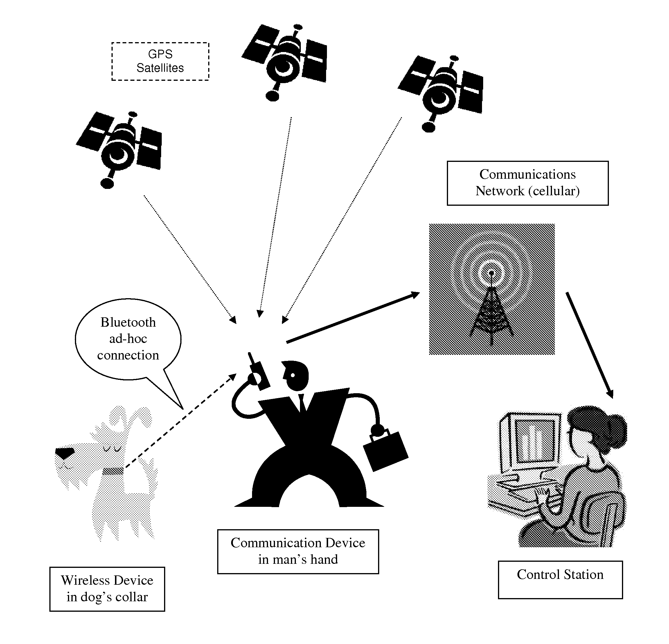
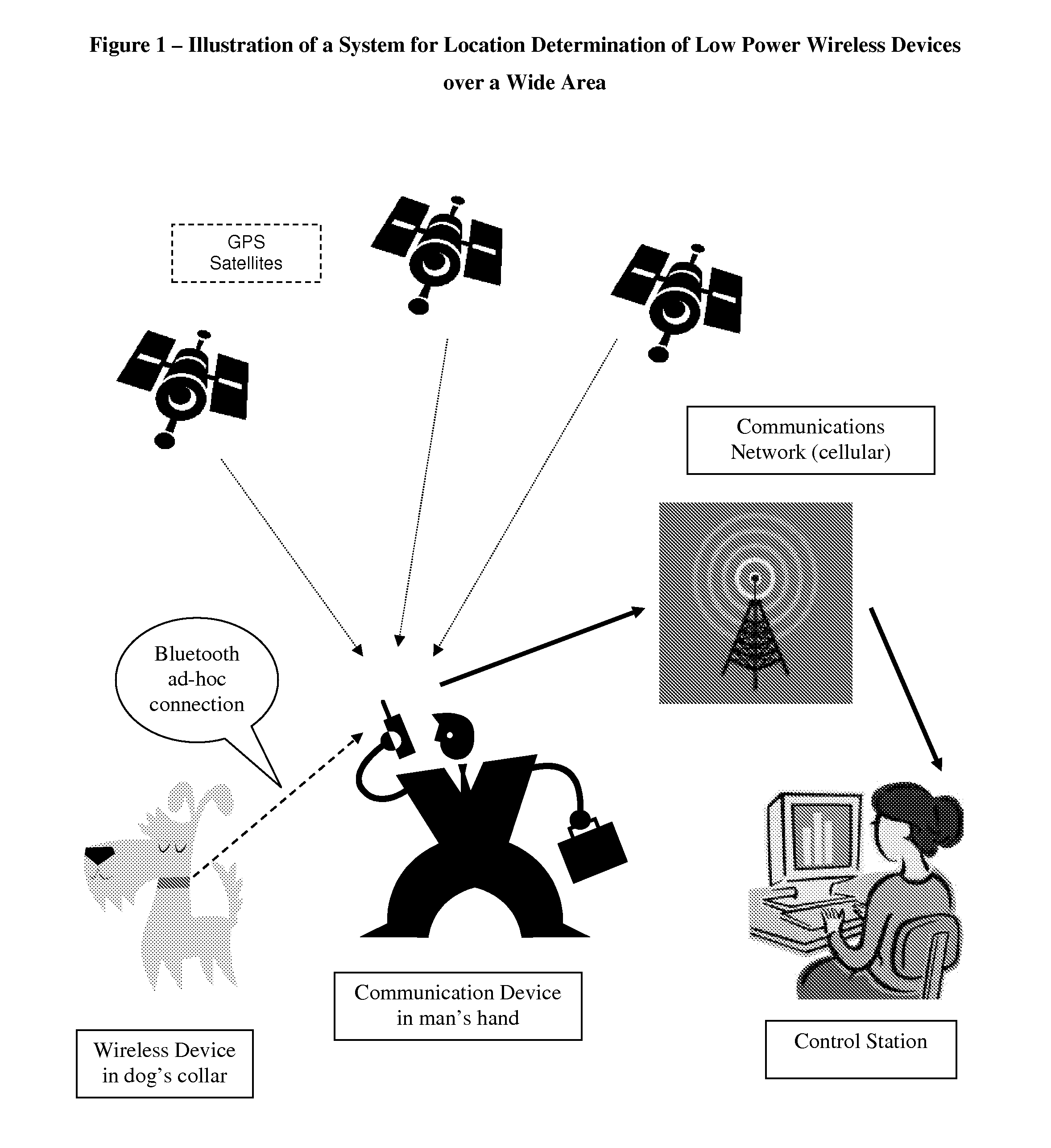
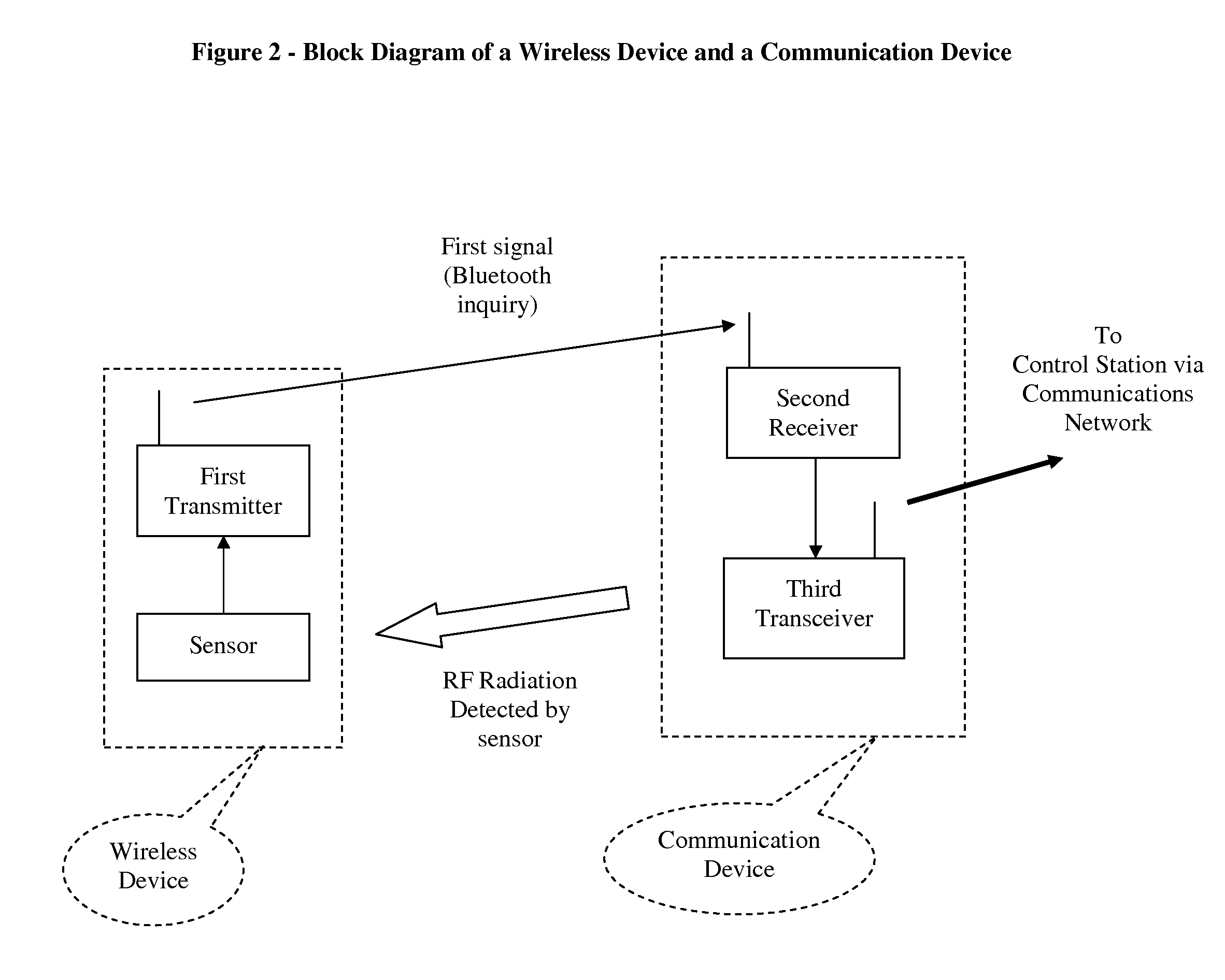
"The invention is a system and method for location determination of wireless devices over a wide area using Bluetooth technology. The system includes a plurality of wireless devices, each with a sensor that detects the presence of nearby communication devices and triggers a first signal. A plurality of communication devices are also included, each with a second and third transceiver. A communications network is connected to the wireless devices and a control station. The control station receives the first signal and identifies the location of the communication device based on the network. The wireless devices can also monitor the status of the communication device and communicate this data to the control station. The invention allows for remote monitoring of wireless devices and enables the identification of specific objects or individuals. The Bluetooth technology allows for low power and low cost sensors to be used. The system can be used in various applications, such as monitoring traffic congestion or animal location tracking."

Problems solved by technology

However, some applications cannot bear the size or price or limited battery life of such a locatable wireless device.
For example, it is not practical to attach a mobile phone to a dog or cat for locating so.
Such a locatable device would be probably considered too large and too expensive and too often requiring battery recharge or replacement.
Still, comprising a GPS receiver in a locatable device can be too expensive, power consuming, and bulky for some applications.
Furthermore, a GPS receiver requires line of sight (LOS) with GPS satellites, thus it's not practical, for example, to place it in a rifle butt, or article in a store, or skier's gear to be tracked upon a snow avalanche.
Still, the wide area transceiver comprised in such mobile devices might be considered too power consuming and too expensive for some applications, such as tracking pets or guns.
When an object is to be located in a local area, such as a building or a manufacturing plant or by a traffic toll checkpoint, short range devices might be well used, yet if an object is required to be located over a wide area, e.g. city or country, as in case of a lost dog or stolen car, short range devices are not suitable unless a dense network or readers / antennas / repeaters is deployed, which is often impractical and uneconomical.
Still, Turner's methods require substantial terrestrial infrastructure, which normally limit the operating area coverage, and generate considerable interrogation transmissions.
However, such as strategy might significantly reduce battery life and cause much noise and interference.
On the other hand, putting receivers and transmitters often to sleep as often done for saving battery power, significantly reduces the chance to establish a rapid ad-hoc connection.
In this context, U.S. Pat. No. 7,155,238 does not teach how can an ad-hoc short range connection between a wireless device and a mobile device be rapidly established, while achieving substantial battery life at a wireless device, for example several years of operation on a small low cost battery.
Even “conditional scan” mode, searching for RF activity on Bluetooth bands, requires much more power from the scanning device and obviously additional power is consumed and dissipated by the inquiring transmitter until an ad-hoc connection is accomplished.
Furthermore, inquiry and inquiry scan operations might last a long time until succeed, due to uncertainties in space (out of range) and time (unsynchronized clocks) and frequencies (different hopping patterns) and mode (which device inquires and which one is scanning for inquiry), between two unconnected Bluetooth devices.
During these long periods, batteries are wasted and interfering signals are generated, undesirably.
Specifically, the process of establishing a wireless connection between unsynchronized frequency hopping devices is not straight forward.
Clearly, such a long discovery time is undesirable for devices installed in driving cars or so, and as indicated before, this period of time can become even longer when such devices move away and often go to sleep in order to save battery power.Paper: Performance of Symmetric Neighbor Discovery in Bluetooth Ad Hoc NetworksDiego Bohman, Matthias Frank, Peter Martini, Christoph ScholzInstitute of Computer Science IV, University of Bonn, R{umlaut over ( )}omerstraβe 164, D-53117 Bonnhttp: / / web.informatik.uni-bonn.de / IV / Mitarbeiter / scholz / 10 Bohman.pdf
Aires' method enables location determination of low power devices, yet it requires a significant terrestrial infrastructure and would be typically restricted to local areas such as a hospital, an airport, a department store, a large legal office, a manufacturing complex, etc', but is not practical for wide area (e.g. city, country) location determination.
In addition, similarly to RFID methods, detection range is quite limited due to the nature of wireless communications employed.
Furthermore, much inefficient radiation is emitted by the relay station / interrogator / reader, since it has no prior knowledge indicating a potential presence of a nearby wireless device, therefore constantly transmitting interrogation signals.
The present are methods described above have not yet provided satisfactory solutions to the problem of location determination of low power wireless devices over a wide area.

Method used


Image

  • Location determination of low power wireless devices over a wide area
  • Location determination of low power wireless devices over a wide area
  • Location determination of low power wireless devices over a wide area

Examples


Embodiment Construction

[0065]The invention will now be described with respect to various embodiments. The following description provides specific details for a thorough understanding of, and enabling description for, these embodiments of the invention. However, one skilled in the art will understand that the invention may be practiced without these details. In other instances, well-known structures and functions have not been shown or described in detail to avoid unnecessarily obscuring the description of the embodiments of the invention.

[0066]The invention is directed to a system and method for location determination of wireless devices, over a wide area, comprised of: a) a plurality of wireless devices, each wireless device comprised of a first short range transmitter and a sensor; b) a plurality of communication devices, each communication device comprised of a second receiver and a third transceiver; c) a communications network; d) a control station coupled to said network; wherein said sensor configu...


PUM


Abstract

The present invention discloses a method and system for location determination of low power wireless devices, over a wide area, utilizing a multitude of communication devices operating on a WAN (Wide Area Network) which can detect signals transmitted by said nearby low power wireless devices, and report this detection to a control station over the WAN. Said station can further locate the reporting communication device by present art methods such as “network based” or “handset based”, and consequently locate the nearby wireless device. Due to the short range nature of the wireless device transmissions, and dynamic mobility of these devices, it is crucial to establish a swift ad-hoc connection between a wireless device and a nearby communication device, still, in order to save battery power and avoid inefficient and interfering transmissions, communications between a wireless device and a communication device are not initiated unitl a sensor comprised in the wireless device detects and a communication device. In a preferred embodiment, the wireless device is Bluetooth and the communication device is a Bluetooth enabled mobile / cellular phone and the sensor detects radiation emitted by the mobile device on non Bluetooth bands.

Description

BACKGROUND OF INVENTION[0001]Location determination of wireless devices is typically employed for locating objects attached with these devices. Such objects may be people, specifically those who might need assistance, animals, pets, vehicles, mobile assets or other valuable items.[0002]The present art provides powerful means for location determination of wireless devices. For example, a mobile (cellular) phone embedded with a GPS (Global Positioning System) receiver can be located practically worldwide. Such a device can be easily carried by a person and operate on a matchbox size battery for several days, before recharged.[0003]However, some applications cannot bear the size or price or limited battery life of such a locatable wireless device. For example, it is not practical to attach a mobile phone to a dog or cat for locating so. Such a locatable device would be probably considered too large and too expensive and too often requiring battery recharge or replacement.[0004]Some pri...

Claims


Application Information

Patent Timeline
Patent Type & Authority Patents(United States)
IPC IPC(8): H04W24/00G08B1/00G08B1/08G08B13/14H04B7/15H04B7/185H04M11/04
CPCG01S5/02G01S5/0205G08B21/0277H04M11/04H04W52/0219H04W28/04H04W64/00H04W76/02H04W84/10H04W84/18H04W52/0216Y02B60/50H04W76/10G01S5/0295
Inventor KATZ
Owner MOBIT TELECOM
Learn More