
Vehicle-mounted power supply system

a power supply system and vehicle technology, applied in the direction of motor/generator/converter stopper, process and machine control, etc., can solve the problems of large variation in the electrical power consumption of the vehicle, unfavorable situations, and the ability to extend beyond the adaptive control range of the power converter

Active Publication Date: 2009-03-17
DENSO CORP
View PDF16 Cites 27 Cited by
  • Summary
  • Abstract
  • Description
  • Claims
  • Application Information

AI Technical Summary

Benefits of technology

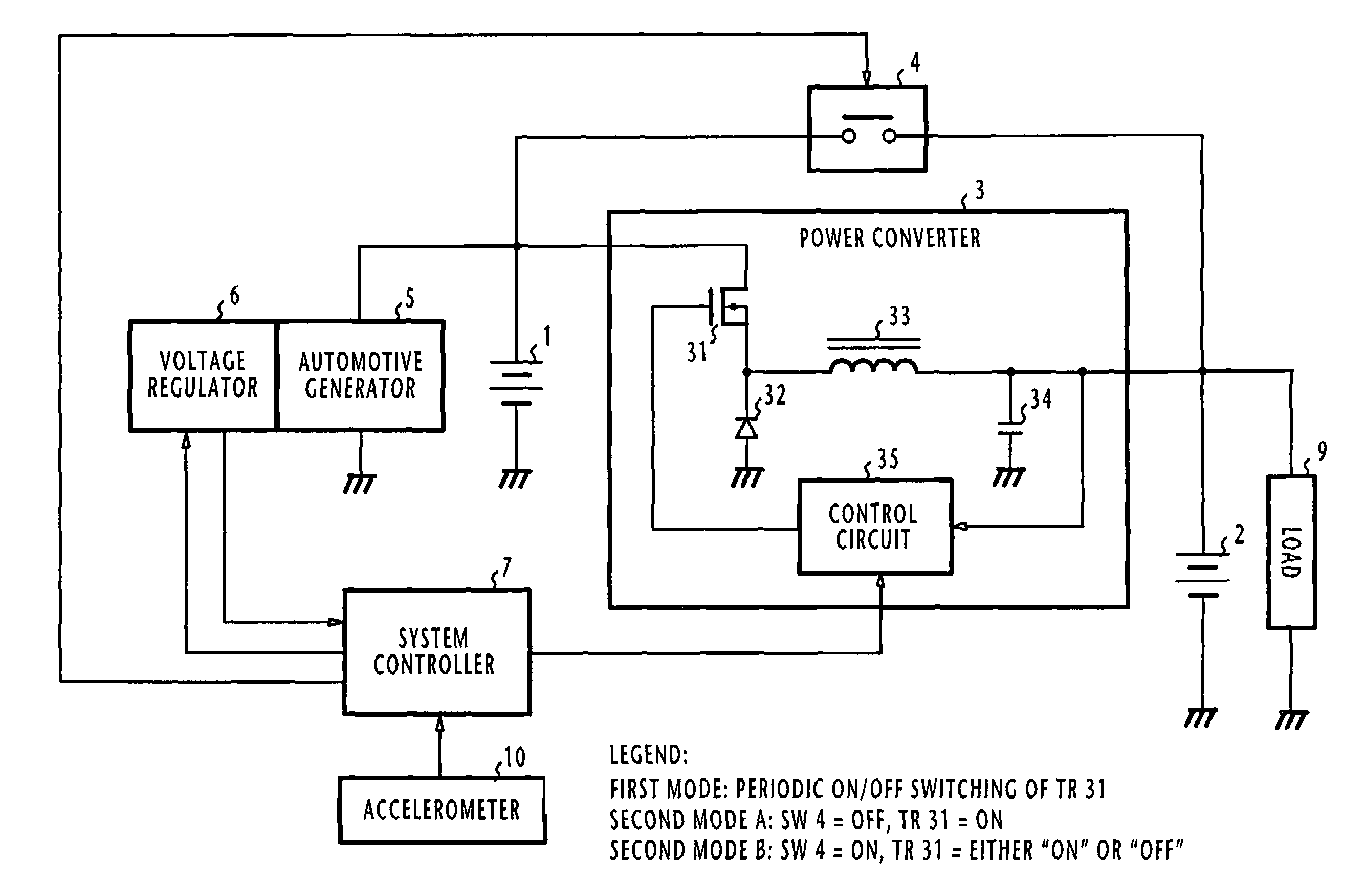
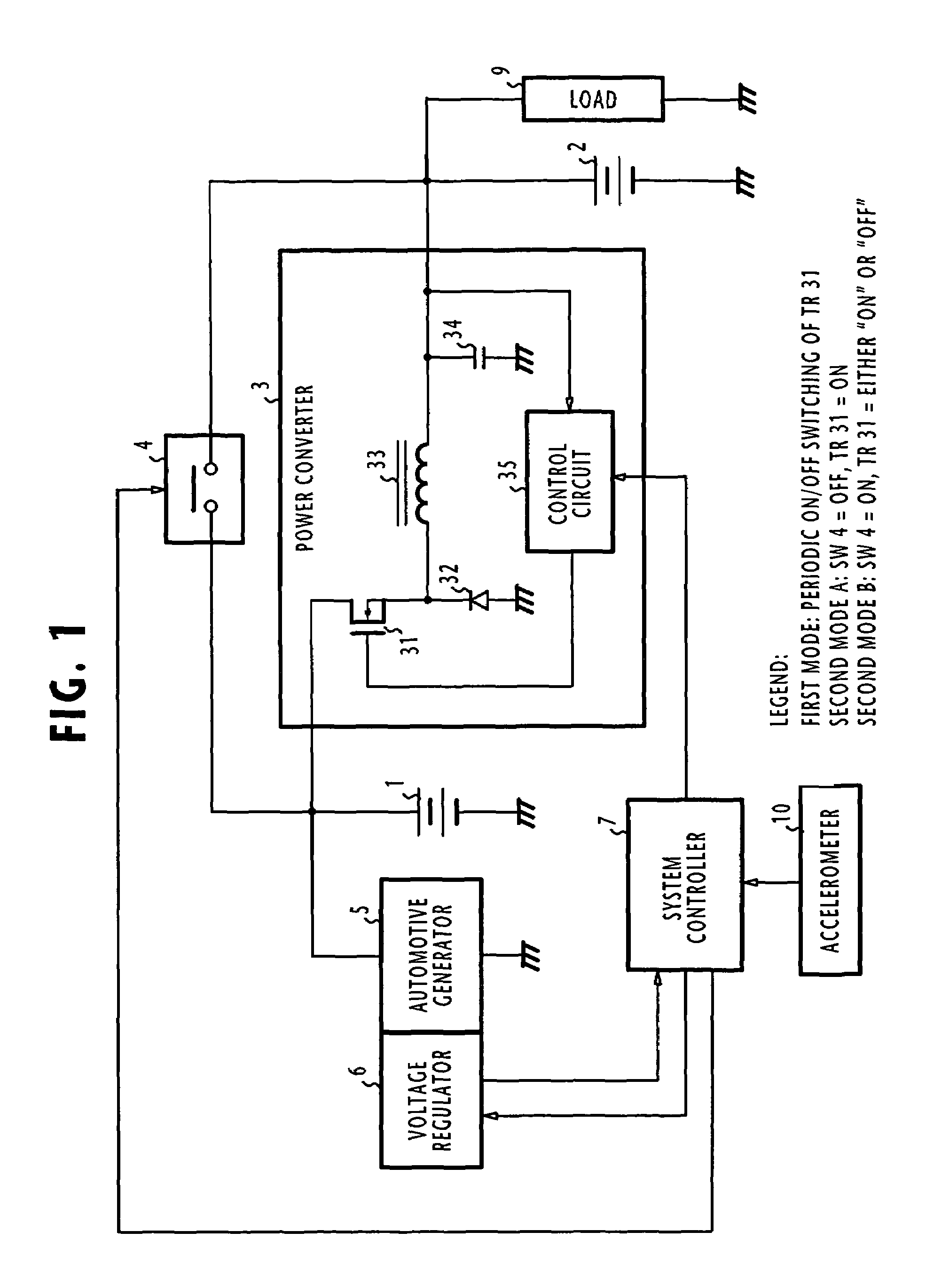
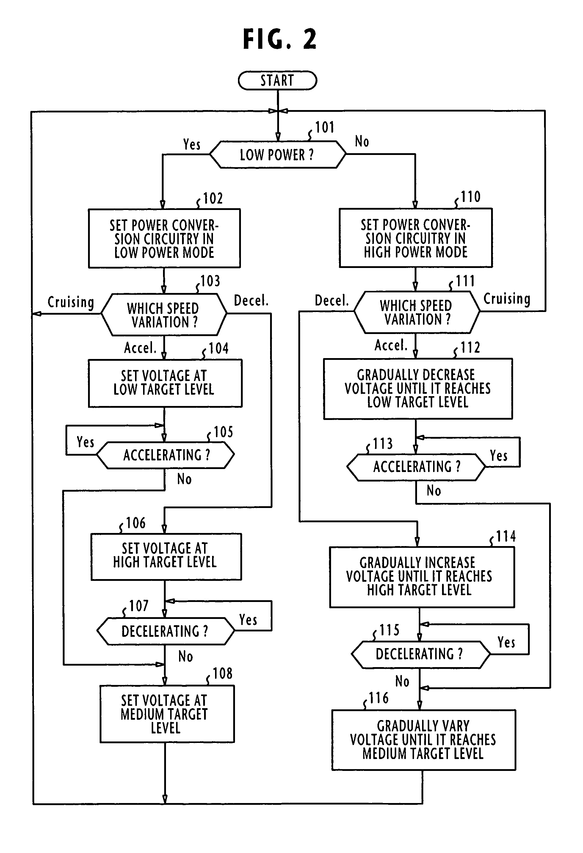
The present invention provides a vehicle-mounted power supply system that can produce a constant voltage under varying operating conditions of the vehicle. This system can supply a constant voltage while ensuring less fuel consumption and reduced emission of harmful gases. It also allows for a compact design for vehicle-mounted power converters. The system includes a first storage battery, an automotive generator, a second storage battery, and power conversion circuitry connected between the two batteries. The power conversion circuitry can operate in two modes: a first mode to maintain the voltage at the second battery at a constant level and a second mode to vary the voltage at the second battery with the voltage at the first battery. The controller can control the generator so that the generated voltage undergoes a transition at a first rate when the power consumption is lower than a specified value and at a second rate lower than the first rate when the power consumption is higher than the specified value.

Problems solved by technology

However, intermittent power regeneration and shutdown could produce a large variation in the electrical power consumption of the vehicle and such variation could eventually exceed beyond the adaptive control range of the power converter.
Thus, the voltage supplied to the headlights and air-conditioning system will undergo large variations, causing such unfavorable situations as fluctuating illumination and varying blower-motor speed.
However, it only adds to the size and capacity of the power converter.

Method used


Image

  • Vehicle-mounted power supply system
  • Vehicle-mounted power supply system
  • Vehicle-mounted power supply system

Examples


Embodiment Construction

[0019]In FIG. 1, a vehicle-mounted power supply system according to one embodiment of the present invention is illustrated. The power supply system comprises two lead-acid batteries 1 and 2. Battery 2 supplies a current to a load circuit 9 and the battery 1 is charged by an automotive generator 5 to a rated voltage higher than the rated voltage of battery 2. Connected between the batteries 1 and 2 is a power converter 3 that performs one-way power conversion from the battery 1 to battery 2. As an option, a switch 4 is connected in parallel with the power converter 3. Preferably, the switch 4 is implemented with a power transistor that is advantageous over the use of a mechanically operated switch that suffers from the well-known bouncing effect, which can result in the generation of a large current.

[0020]Power converter 3 and switch 4 constitute power conversion circuitry. Depending on power consumption of the electrical load 9, the power conversion circuitry operates in one of firs...


PUM


Abstract

In a vehicle-mounted power supply system, the automotive generator generates a voltage for charging a first battery. Power conversion circuitry is connected between the first battery and a second battery that is connected to an electrical load to operate in a first mode or in a second mode when power consumption of the load is lower or higher than a specified value, respectively. In the first mode, the power conversion circuitry maintains the voltage at the second battery at a substantially constant level and in the second mode, the voltage at the second battery varies with the voltage at the first battery. In response to a vehicle speed variation, the automotive generator is controlled so that its output voltage is varied at a first rate when power conversion is performed in the first mode and varied at a second rate lower than the first rate when power conversion is performed in the second mode.

Description

CROSS-REFERENCE TO RELATED APPLICATION[0001]This application is based on Japanese Patent Application 2004-241777, filed Aug. 23, 2004, which is hereby incorporated by reference.BACKGROUND OF THE INVENTION[0002]1. Field of the Invention[0003]The present invention relates to a vehicle-mounted power supply system for charging a storage battery and supplying power to electrical loads.[0004]2. Description of the Related Art[0005]As disclosed in Japanese Patent Publications 6-296332 and 2002-238103, a vehicle-mounted power supply system is controlled to generate electricity according to the driving condition of the vehicle for improving fuel consumption and emission of noxious gases. In particular, the vehicle-mounted power supply system is operated in different modes according to the driving condition of the vehicle. During deceleration, power regeneration is performed by converting the momentum of the vehicle to electric energy and returning it to a storage battery, and during accelerat...

Claims


Application Information

Patent Timeline
Patent Type & Authority Patents(United States)
IPC IPC(8): G01R31/36
CPCB60L7/10H02J1/08G01R31/36H02J7/14
Inventor TANIGUCHI, MAKOTOTANAKA, KATSUNORI
Owner DENSO CORP
Learn More