Turbocharger with variable nozzle

a variable nozzle and turbocharger technology, which is applied in the direction of liquid fuel engines, machines/engines, reaction engines, etc., can solve the problems of not particularly pointed out, difficult to quickly obtain a turbo effect, and hardly work of the turbocharger, and achieve the effect of suppressing the heating of the radially expanded portion

a variable nozzle and turbocharger technology, which is applied in the direction of liquid fuel engines, machines/engines, reaction engines, etc., can solve the problems of not particularly pointed out, difficult to quickly obtain a turbo effect, and hardly work of the turbocharger, and achieve the effect of suppressing the heating of the radially expanded portion

US7509804B2Active Publication Date: 2009-03-31IHI CORP

Image

  • Turbocharger with variable nozzle
  • Turbocharger with variable nozzle
  • Turbocharger with variable nozzle

Examples


Embodiment Construction

[0030]The description will be given of a preferable embodiment in accordance with the present invention with reference to the accompanying drawings. Meanwhile, the same reference numerals are attached to common portions in each of the drawings, and the repeated description will be omitted.

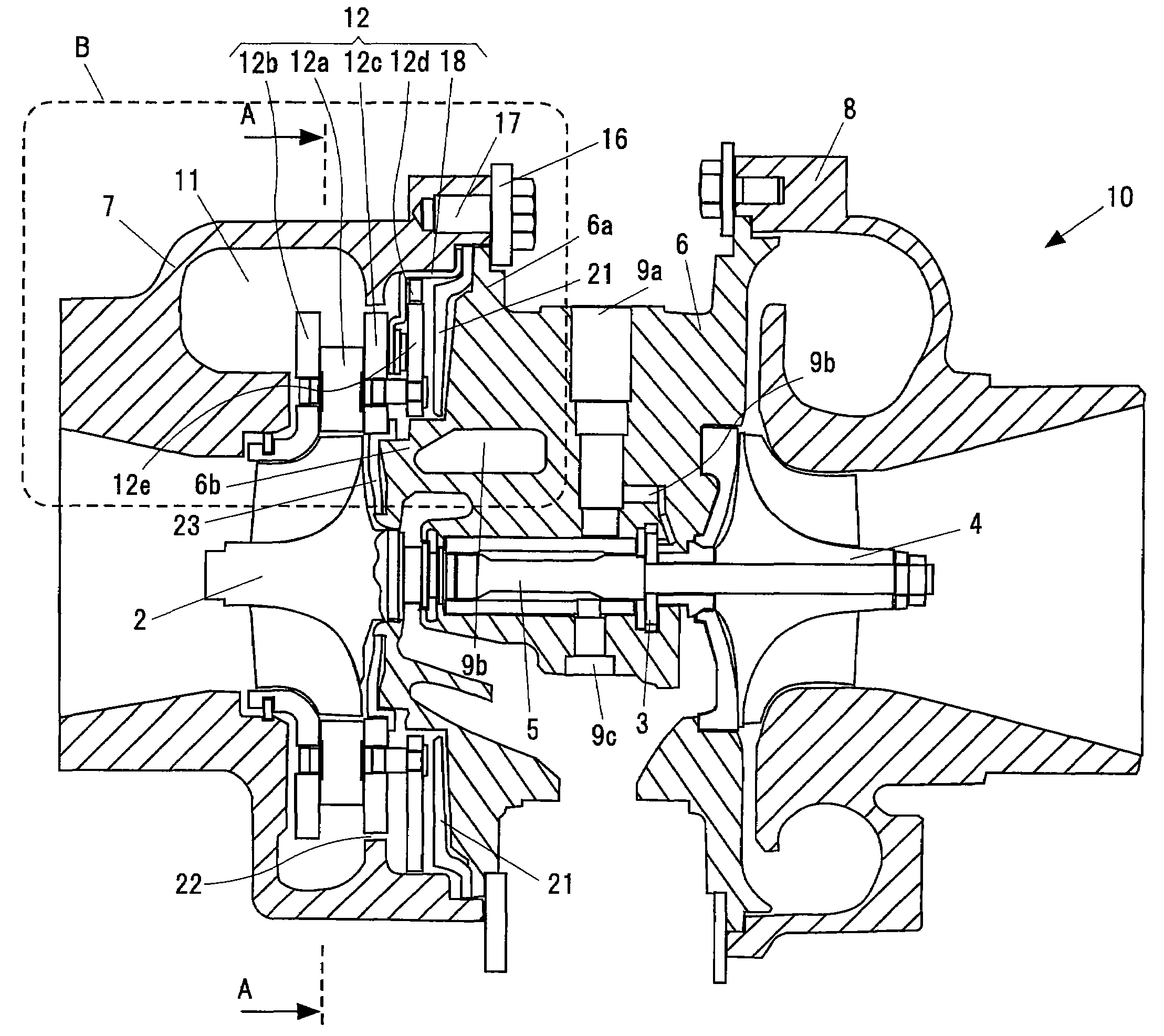
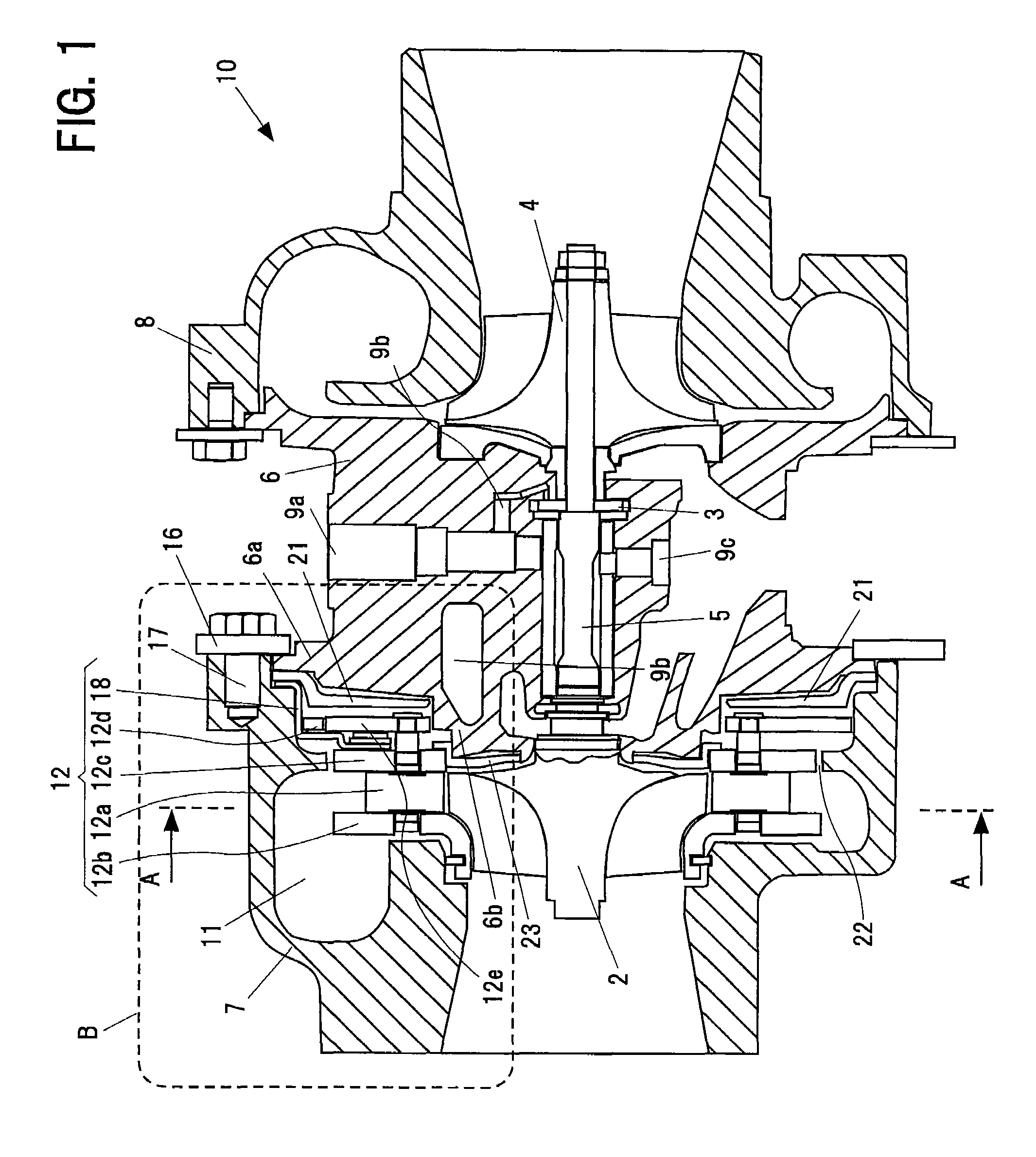
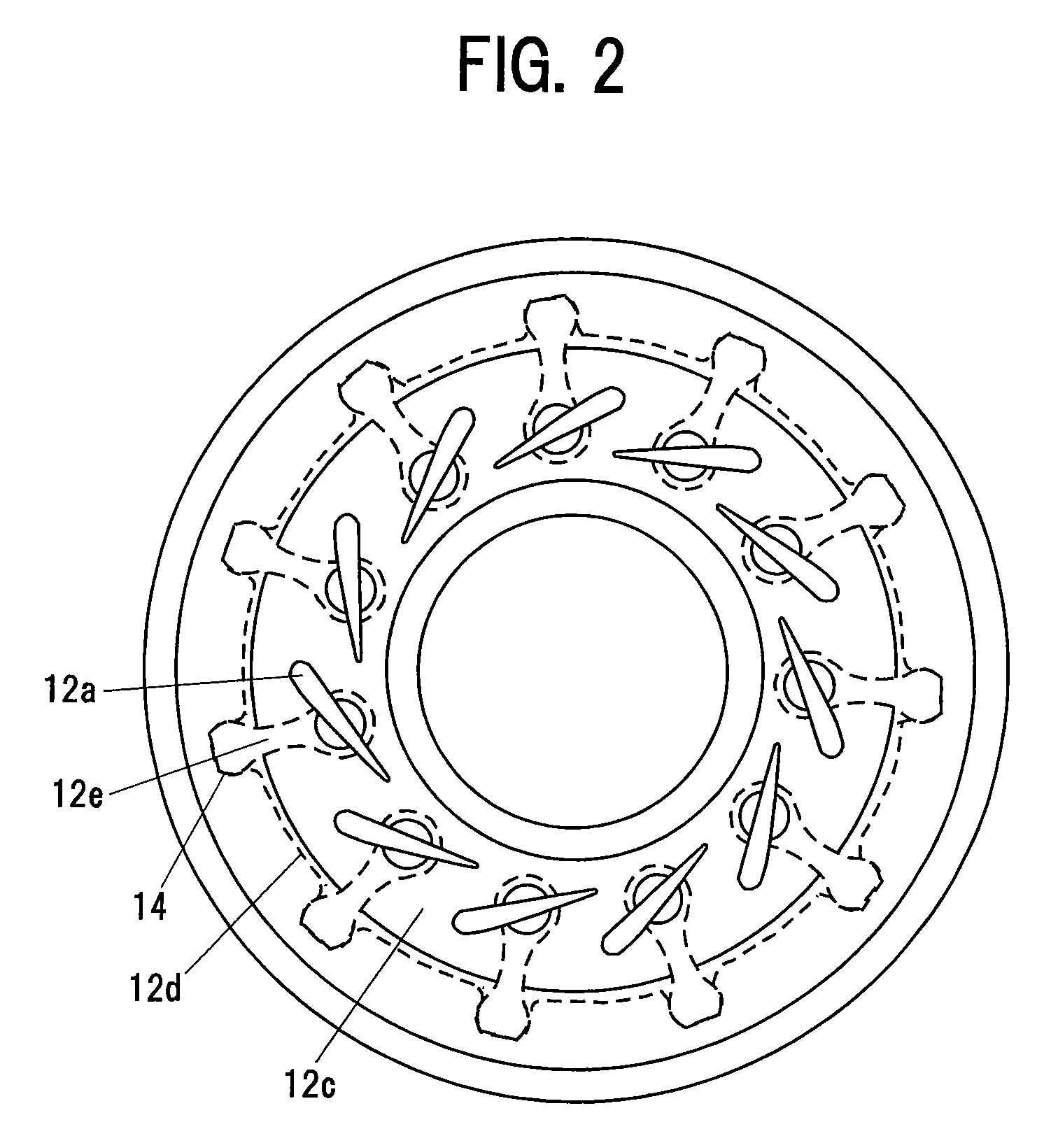
[0031]FIG. 1 is a cross sectional view in an axial direction of a turbocharger 10 with a variable nozzle showing an embodiment in accordance with the present invention. FIG. 2 is a view along a line A-A in FIG. 1, and shows a variable nozzle mechanism 12 adjusting a flow rate of an exhaust gas from an engine to a turbine.

[0032]A turbocharger 10 with a variable nozzle shown in FIG. 1 is provided with a turbine impeller 2 rotationally driven by the exhaust gas from the engine, a compressor impeller 4 rotationally driven by a driving force of the turbine so as to supply a compressed air to the engine, a shaft 5 coupling the turbine impeller 2 and the compressor impeller 4, a bearing housing 6 rotatabl...


PUM


Abstract

A turbocharger with a variable nozzle has a turbine impeller, a compressor impeller, a shaft coupling the turbine impeller and the compressor impeller, a bearing housing rotatably supporting the shaft, and a turbine housing accommodating the turbine impeller. The turbocharger further includes a variable nozzle mechanism, provided in a compressor impeller side in a radial-direction outer side of the turbine impeller, for adjusting a flow rate of an exhaust gas directed to the turbine impeller. The bearing housing has a radially expanded portion that extends to a radial-direction outer side to be coupled to the turbine housing at a radial-direction outer side portion thereof such that the variable nozzle mechanism is accommodated between the turbine housing and the radially expanded portion. Between the variable nozzle mechanism and the radially expanded portion, a heat shield plate is provided for preventing a heat transmission between them.

Description

BACKGROUND OF THE INVENTION[0001]1. Technical Field of the Invention[0002]The present invention relates to a turbocharger with a variable nozzle, and more particularly to a turbo charger with a variable nozzle having a mechanism capable of suppressing a temperature increase of a compressor side thrust bearing or the like.[0003]2. Description of the Related Art[0004]A turbocharger is a supercharger used for a high output of an engine, for example, for a motor vehicle. In the turbocharger, a compressed air is supplied to the engine from a compressor by rotating a turbine impeller by exhaust energy of the engine, and rotating a compressor impeller by an output of the turbine. Accordingly, it is possible to achieve a supercharging state over a natural air supply in the engine.[0005]In the turbocharger, at the time of low speed revolution of the engine, the turbine hardly works due to a low exhaust flow rate. Accordingly, in the engine capable of operating at a high speed revolution, it ...

Claims


Application Information

Patent Timeline
31 Mar 2009
Publication
US7509804B2
IPC
F02D23/00; F01D17/12; F01D17/18; F01D25/08
CPC
F01D17/165; F01D25/162; F05D2220/40; F05D2260/231; F02B37/22; F02B37/12; F01D17/16; F02D9/02
Inventors
KOBAYASHI, TAKAHIRO