Trigger switch

a technology of trigger switch and trigger, which is applied in the field of trigger switch, can solve the problems of increasing the frictional wear of the contacts, shortening the working life of the contacts, and increasing the price of the power hand tool, and achieves the effect of simple structur

Active Publication Date: 2009-03-31
SATORI ELECTRIC
View PDF7 Cites 26 Cited by
  • Summary
  • Abstract
  • Description
  • Claims
  • Application Information

AI Technical Summary

Benefits of technology

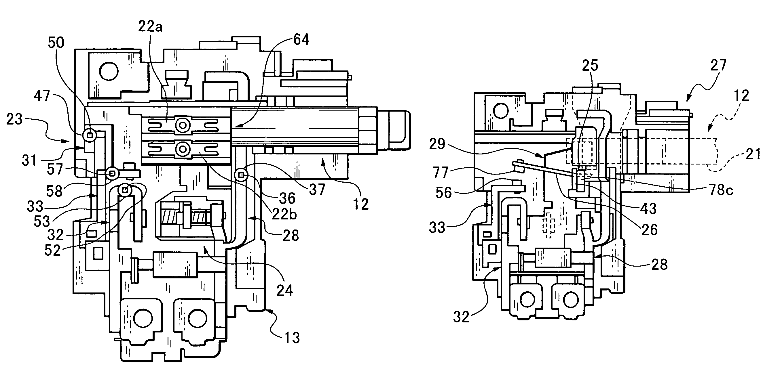
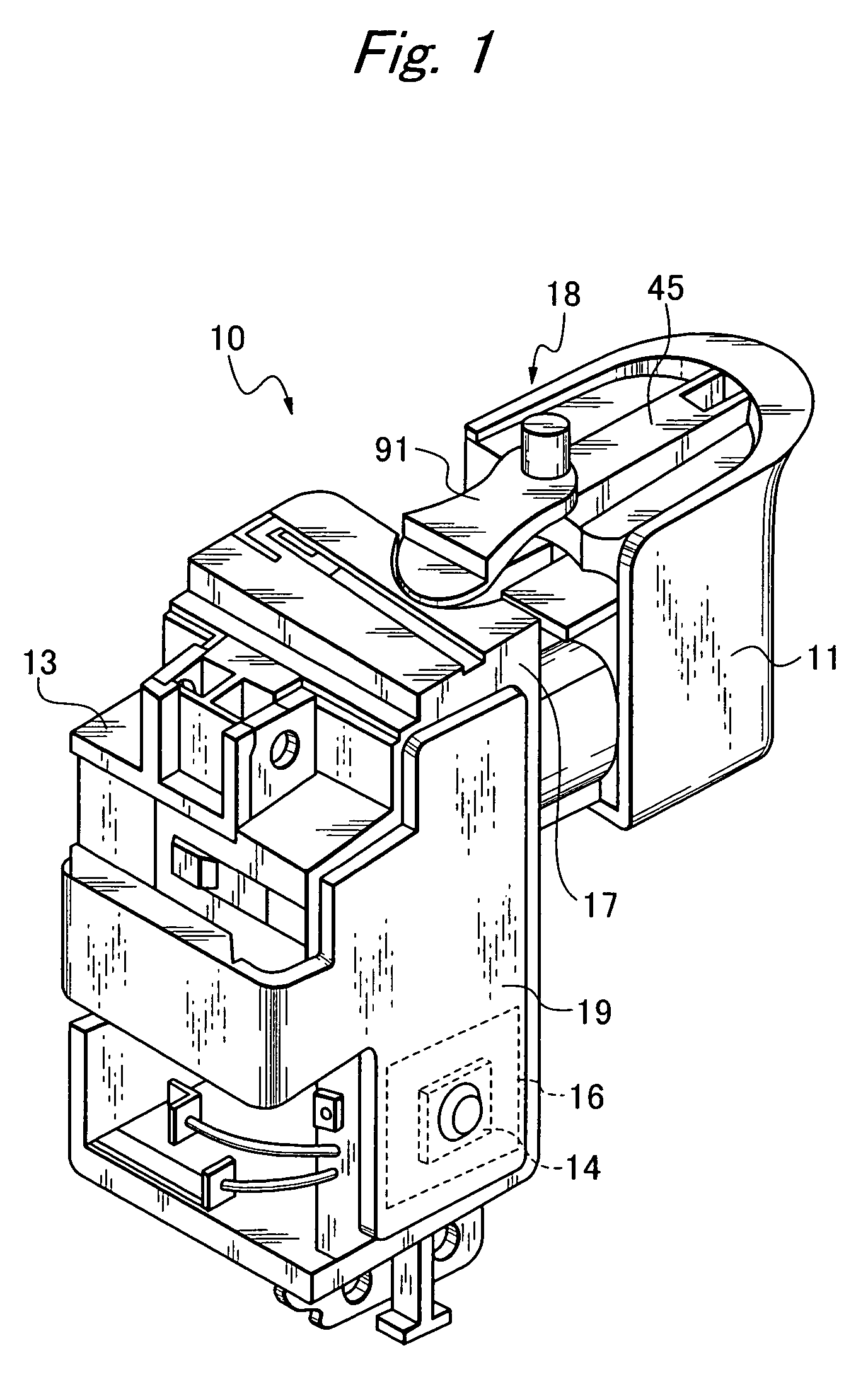
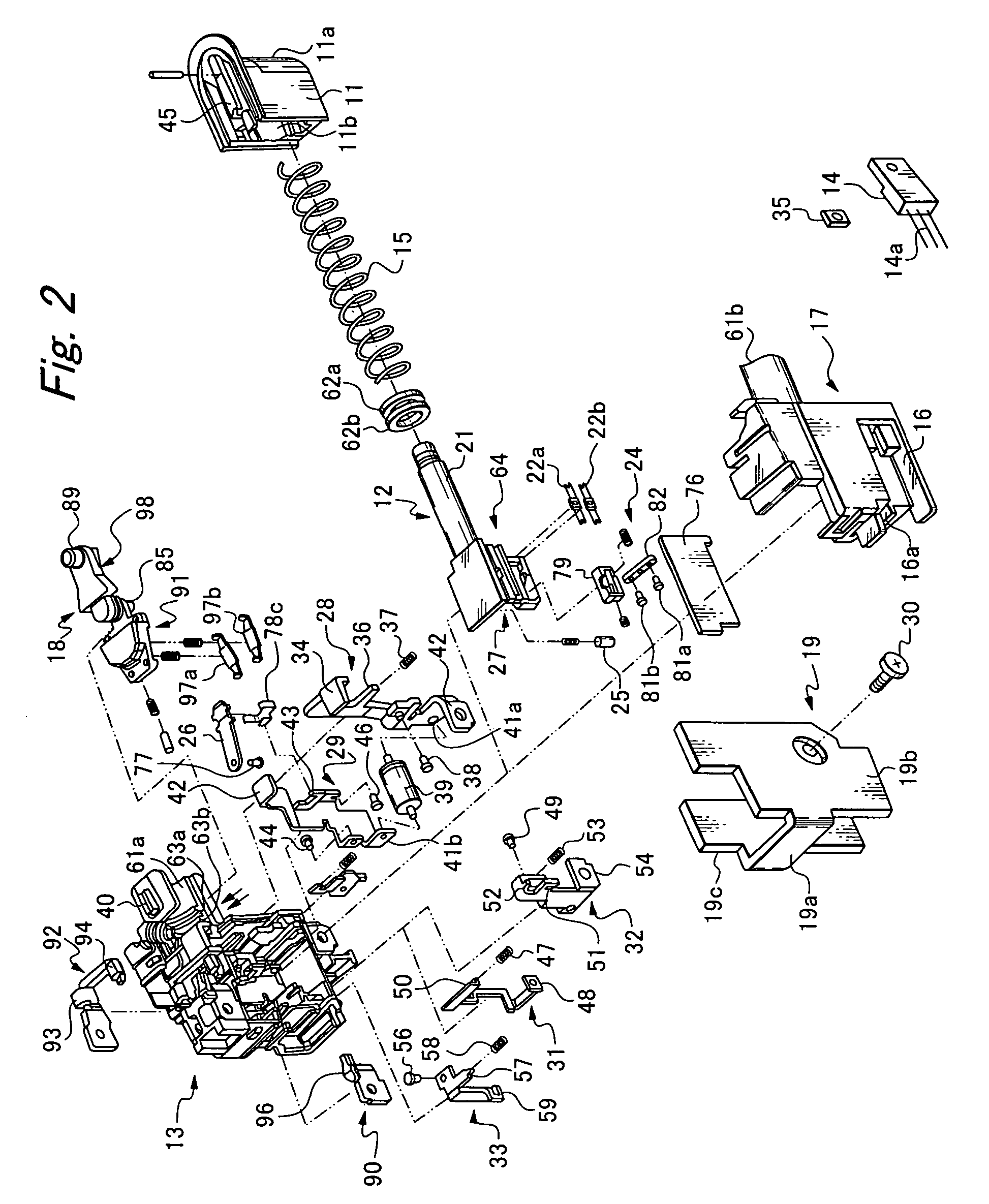
[0012]Accordingly, it is an object of the present invention to solve the above-described problems of the conventional art and to provide, in a simple structure, a trigger switch capable of suppressing bouncing when the contacts are switched ON and OFF.
[0013]In addition, it is another object of the present invention to provide a trigger switch having circuitry that is capable of eliminating an electrical potential difference between the contacts of the switches when the power switch or the short-circuit switch turns ON or OFF and lighting the LED before the motor rotates so as to illuminate a workpiece before work thereon is begun, as well as to provide a simple technique for high-speed rotation control of the motor.
[0014]Furthermore, it is another and further object of the present invention to provide, in a trigger switch mounting a heat-generating member on the outside of a switch mechanism and which is equipped with a heat slinger to absorb heat generated by the heat-generating member, a structure of the heat slinger that is capable of absorbing heat uniformly when installed in a power hand tool, a mechanism that blocks dust from getting inside the switch mechanism from a gap between a sliding shaft operated externally and a support member that supports the sliding shaft, and a switch mechanism that provides improved vibration resistance and motor brake performance under harsh conditions involving heavy vibration.

Problems solved by technology

Therefore, when the power switch and the short switch turn ON and OFF, the switching element also is turned ON and OFF, and thus an electric potential difference arises between the contacts of the power switch or the short switch, generating a spark when the power switch or the short switch is turned ON or OFF, which increases frictional wear on the contacts and in turn shortens the working life of the contacts.
This addition of a component increases the price of the power hand tool or the like and hinders efforts to make to such tools more compact and thus easier to handle and more easily portable.
As a result, the temperature of only the space on the heat slinger side rises, imparting an unpleasant feel to the place where the power hand tool is gripped.
In addition, because the sliding shaft for external control of the switching protrudes from the case and the trigger is mounted on the outside tip of the sliding shaft, dust gets inside the switch mechanism from a gap between the sliding shaft and a support member supporting the sliding shaft when the sliding shaft slides, which can cause malfunctions of the switch mechanism.
Furthermore, because the trigger switch is constituted so that the switching lever switches to either one side or the other so that the trigger stopper of the trigger does not engage even if the trigger is retracted while the switching lever is in the neutral position, the trigger cannot be operated when the lever is in the neutral OFF position and thus does not function as the safety mechanism that it is originally intended to be.

Method used


Image

  • Trigger switch
  • Trigger switch
  • Trigger switch

Examples


second embodiment

[0134]FIG. 27 shows a trigger switch according to a second embodiment of the present invention. The switch mechanism and switch operation mechanism of the trigger switch are the same as those of the first embodiment described above, with only the structure of the heat slinger being different from that of the first embodiment. Accordingly, a description is given of the heat slinger whereas a description of structures other than the heat slinger is omitted.

[0135]In other words, a heat slinger 19A of the present embodiment is formed as a single flat plate that covers the sidewall surfaces of the cover 17 as shown in the diagram, and secured together with the control element (FET) 14 by the screw 30. The inside surface of the heat slinger 19A directly contacts the front surface of the FET 14 contained in the FET mount 16, and thus is able to disperse evenly the heat generated by the FET 14. Forming the heat slinger 19A as a single flat plate in the foregoing manner enables the bulkiness...


PUM

PropertyMeasurementUnit
voltageaaaaaaaaaa
DC poweraaaaaaaaaa
resistanceaaaaaaaaaa

Abstract

To provide a trigger switch having a simple structure that is capable of reducing bouncing when the contacts are switched ON / OFF, the trigger switch includes a switch mechanism integrated in a single assembly a power control unit that turns a plurality of switches provided on the switch mechanism ON / OFF depending on a degree of retraction of the control unit by moving a pressing member over a top of a seesaw-shaped switching bar, a motor brake and control element short-circuit unit that drives a movable armature having two short-circuit contacts and is sandwiched and held between two springs, and a speed control unit that slides a plurality of moving contacts disposed in parallel over sliding contacts disposed on a sliding circuit substrate so as to control both the supply of power and a control element, and thus control the rotation speed of a motor.

Description

BACKGROUND OF THE INVENTION[0001]1. Field of the Invention[0002]The present invention relates to a trigger switch mounted in a power hand tool such as an electric-powered drill or the like, and more particularly, to a trigger switch that switches a switch mechanism installed inside the power tool case according to the sliding of a control unit provided on the outside of the case.[0003]2. Related Art[0004]Conventionally, as a switch circuit for a trigger switch, there is known, for example, the trigger switch circuit for power tool disclosed in JP-A-11-144545. That is, the trigger switch circuit controls the rotation of a motor using a moving contact that moves in tandem with the retraction of an operating lever, such that, when the operating lever is in an OFF state, a motor brake switch is turned ON, the motor is shorted and the brake activated. When the operating lever is pulled in an ON state, the motor brake switch is turned OFF, a power switch is turned ON, and electric power i...

Claims


Application Information

Patent Timeline
Patent Type & Authority Patents(United States)
IPC IPC(8): H01H13/02
CPCH01H9/04H01H9/063H01H9/52
Inventor INAGAKI, ISAOKOWAKI, SATORUMASUDA, SHINICHIKOMATSU, HIDEYUKI
Owner SATORI ELECTRIC
Why Eureka
Try Eureka