Power management of radio transceiver elements

a radio transceiver and power management technology, applied in power management, wireless commuication services, high-level techniques, etc., can solve the problems of not providing power saving modes and periods that maximally extend battery life, specific suggestions for maximizing power savings, and consuming different amounts of power in radio receivers. , to achieve the effect of reducing power consumption, minimizing power consumption, and increasing complexity

Inactive Publication Date: 2009-03-31
AVAGO TECH INT SALES PTE LTD
View PDF5 Cites 29 Cited by
  • Summary
  • Abstract
  • Description
  • Claims
  • Application Information

AI Technical Summary

Benefits of technology

[0013]One advantage of the present invention is that power consumption utilizing traditional circuit designs may be minimized. Further, a designer implementing the present invention may determine through experimentation for his or her particular design, that power consumption may be reduced by designing circuit component blocks having greater complexity and operational power consumption but that have faster power cycle time characteristics. For example, if a first design has a power cycle characteristic that does not allow it to be powered down and back up during a period in which a transceiver is in a transmit mode of operation, a second design, while consuming more power during a receive mode of operation but having a shorter power cycle time, may be powered down during the transmit mode of operation thereby consuming less power on average. These and other advantages may be better understood in view of the description of the figures that follow.
is that power consumption utilizing traditional circuit designs may be minimized. Further, a designer implementing the present invention may determine through experimentation for his or her particular design, that power consumption may be reduced by designing circuit component blocks having greater complexity and operational power consumption but that have faster power cycle time characteristics. For example, if a first design has a power cycle characteristic that does not allow it to be powered down and back up during a period in which a transceiver is in a transmit mode of operation, a second design, while consuming more power during a receive mode of operation but having a shorter power cycle time, may be powered down during the transmit mode of operation thereby consuming less power on average. These and other advantages may be better understood in view of the description of the figures that follow.

Problems solved by technology

Each of the various stages of the radio receiver consume differing amounts of power.
The current designs and proposals, however, do not provide specific suggestions for maximizing the amount of power savings and do not provide for power saving modes and periods that maximally extend battery life.

Method used


Image

  • Power management of radio transceiver elements
  • Power management of radio transceiver elements
  • Power management of radio transceiver elements

Examples


Embodiment Construction

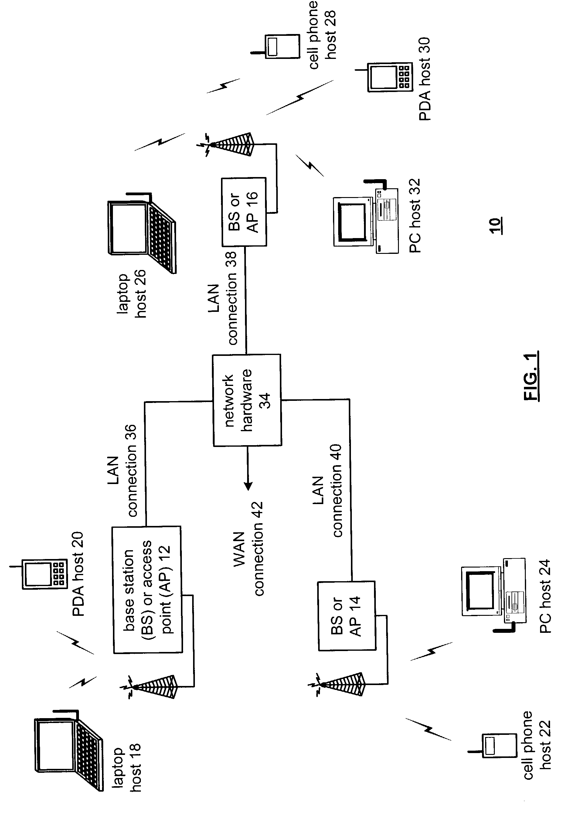
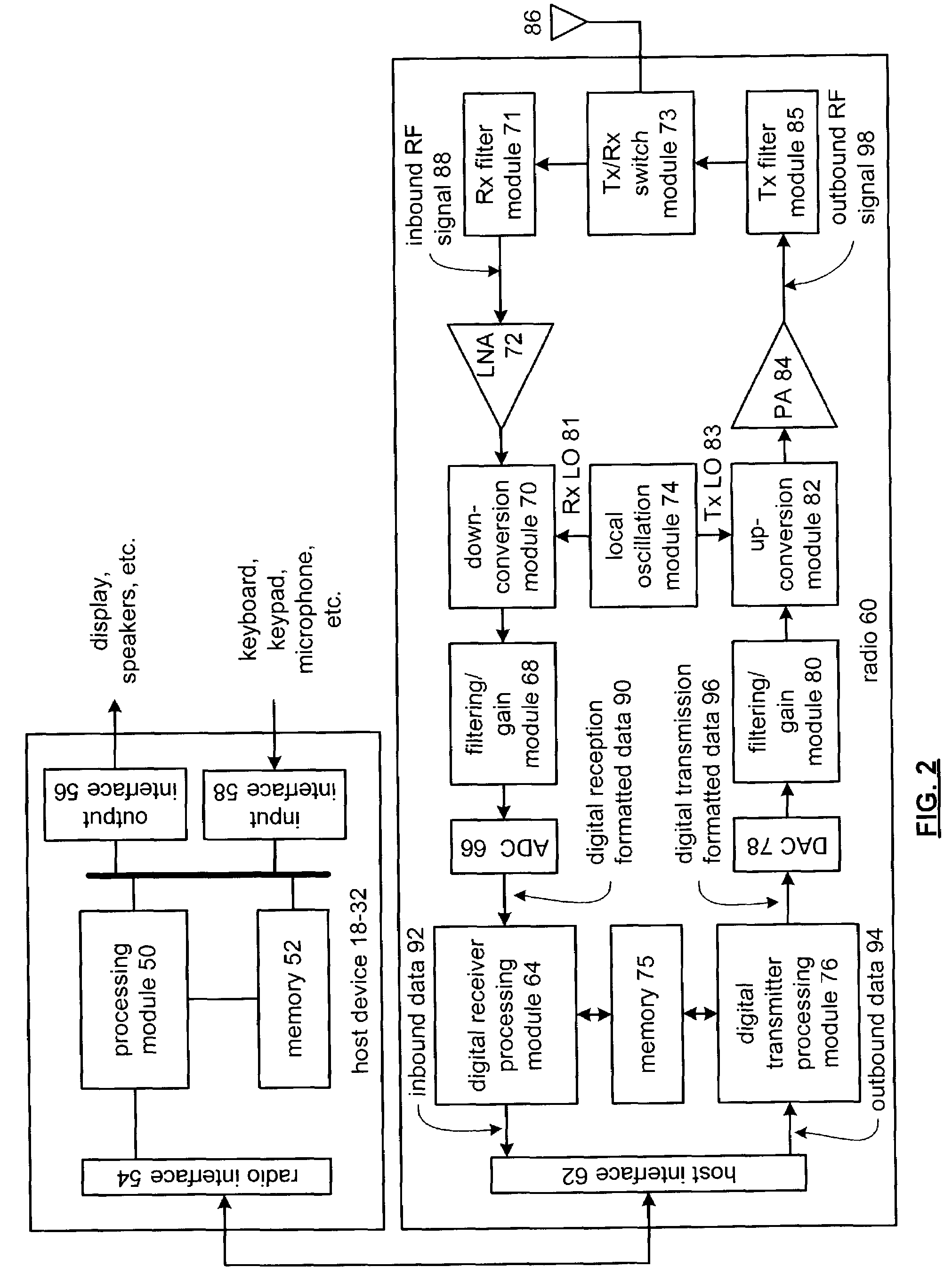
[0024]FIG. 1 is a schematic block diagram illustrating a communication system 10 that includes a plurality of base stations or access points 12-16, a plurality of wireless communication devices 18-32 and a network hardware component 34. The wireless communication devices 18-32 may be laptop host computers 18 and 26, personal digital assistant hosts 20 and 30, personal computer hosts 24 and 32 and / or cellular telephone hosts 22 and 28. The details of the wireless communication devices will be described in greater detail with reference to FIG. 2.

[0025]The base stations or access points 12-16 are operably coupled to the network hardware 34 via local area network connections 36, 38 and 40. The network hardware 34, which may be a router, switch, bridge, modem, system controller, etc., provides a wide area network connection 42 for the communication system 10. Each of the base stations or access points 12-16 has an associated antenna or antenna array to communicate with the wireless commu...


PUM


Abstract

A radio receiver includes a power control module for selectively powering down and powering up radio receiver elements in between known communication periods according to one aspect of the present invention. According to a second aspect of the invention, the radio receiver operates in a low power mode of operation and periodically “sniffs” to determine whether an access point has messages or communication signals to transmit to it.

Description

CROSS-REFERENCE TO RELATED APPLICATION[0001]This application claims priority to and incorporates by reference U.S. Provisional Application entitled, “Power Management of Radio Receiver Elements”, having a Ser. No. of 60 / 403,224 and a filing date of Aug. 12, 2002.BACKGROUND OF THE INVENTION[0002]1. Technical Field of the Invention[0003]This invention relates generally to wireless communication systems and more particularly to radio frequency integrated circuits used in such wireless communication systems.[0004]2. Description of Related Art[0005]Communication systems are known to support wireless and wire lined communications between wireless and / or wire lined communication devices. Such communication systems range from national and / or international cellular telephone systems to the Internet to point-to-point in-home wireless networks. Each type of communication system is constructed, and hence operates, in accordance with one or more communication standards. For instance, wireless co...

Claims


Application Information

Patent Timeline
Patent Type & Authority Patents(United States)
IPC IPC(8): H04M1/00H04B1/16H04M1/73
CPCH04B1/1615H04W52/0238H04W52/0283Y02B60/50Y02D30/70
Inventor KARAOGUZ, JEYHAN
Owner AVAGO TECH INT SALES PTE LTD
Why Eureka
Try Eureka