
Device for the preparation execution and evaluation of a non-destructive analysis

a non-destructive analysis and device technology, applied in the direction of fluid pressure measurement, testing circuit, instruments, etc., can solve the problems of not being able to determine the depth of the defect, planning and performing ultrasonic inspection is a very complex procedure, and combined inspection methods such as weld seam testing consisting of ultrasonic and hardness inspection cannot be performed using a common user interface, etc., to achieve easy operation and manufacturing. , the effect of low cos

Active Publication Date: 2009-03-31
GE INSPECTION TECH LP
View PDF3 Cites 2 Cited by
  • Summary
  • Abstract
  • Description
  • Claims
  • Application Information

AI Technical Summary

Benefits of technology

[0012]The invention provides an apparatus for preparing, performing and evaluating a non-destructive inspection that is connectable with any test instrument. It is intended that a superior abstract inspection planning that integrates the various test instruments, evaluation and analysis methods be carried out. The apparatus is intended to be easy to operate and manufacturable at a low cost.
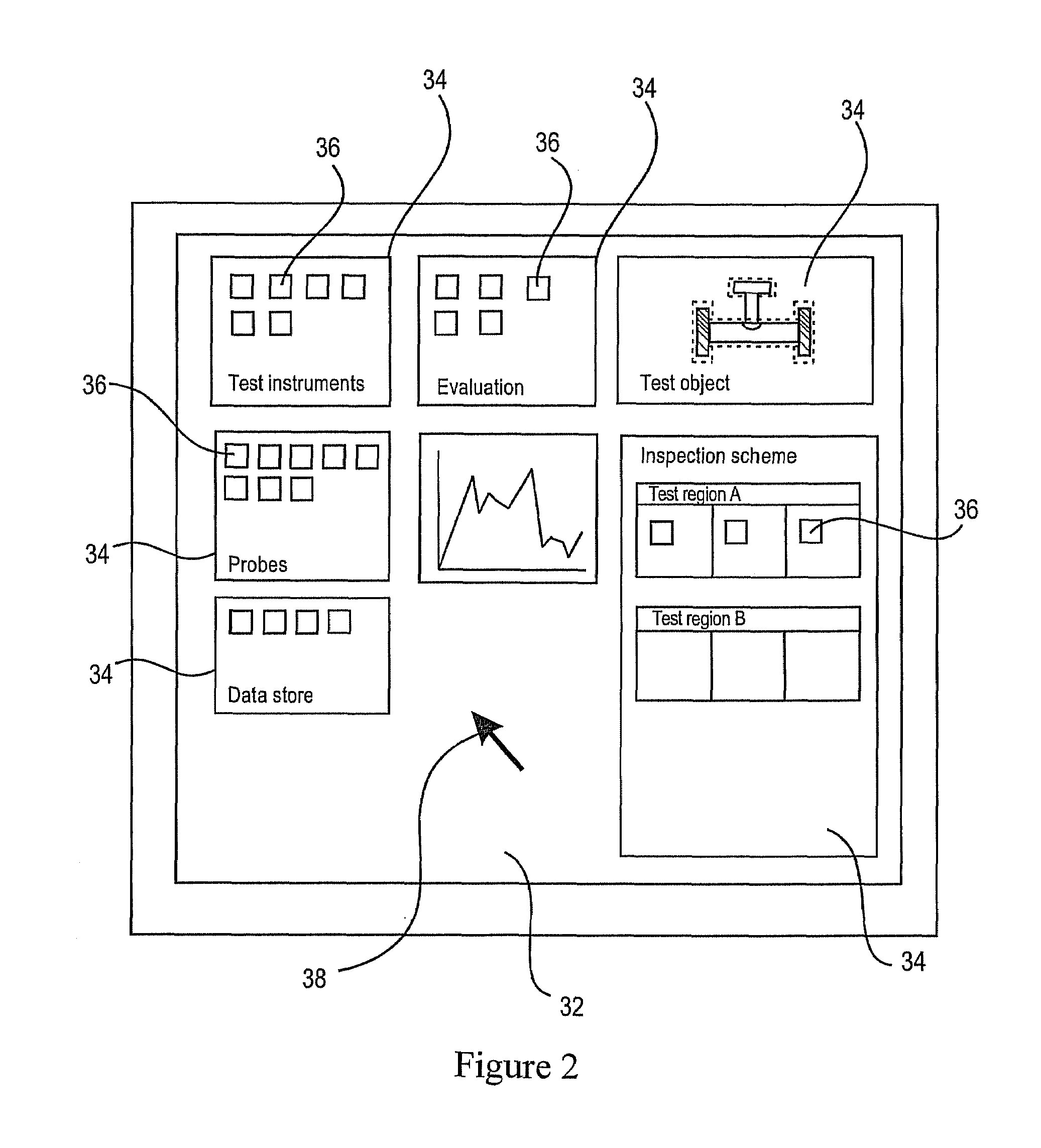
[0031]The invention also makes it possible to establish a test plan beforehand using only one determined handheld test instrument, for example a self-sufficiently operated handheld test instrument that may be used with different probes and by means of which various test methods may be performed. This may be a reasonable choice when ultrasonic inspection is for example to be followed by surface hardness inspection with an eddy current inspection having to be carried out last. Accordingly, all the necessary settings may be carried out on the computer within the scope of the test plan. A test scheme may be established which the test operator merely needs to follow. This substantially facilitates work and inspection since the quite time-consuming in situ setting of the test instruments may be eliminated. Moreover, it is made certain that the input requirements are exactly met. This makes testing easier for inexperienced test operators in particular.
[0032]It is also possible to determine in advance the suitable way to visualize and evaluate the test values measured. This presents the advantage that standardized visualization and evaluation methods may be introduced, which in turn makes in situ inspection easier for the test operator by virtue of the presetting that has been made.
[0051]Another major advantage is that the user will be given the ability to dynamically load and activate newly developed future plugins. What matters for the configuration is not the appearance of frame buttons or text fields but the structure of functions and groups of functions. This makes it possible to perfectly adapt future systems to their purpose of utilization, which last but not least also means ergonomic improvement to the user.
[0055]Accordingly, it is possible for the user to quickly and readily prepare a certain test instrument for a pending inspection using the apparatus of the invention on the one side and to thereby determine which test region is to be inspected by means of which test method and with which settings. If the tasks to be performed are more complicated, inspection planning may also include various test instruments, which is just as easy and simple to realize.

Problems solved by technology

It is not possible to determine the depth of the defect with this technique.
Accordingly, planning and performing an ultrasonic inspection is a very complex procedure requiring on the one hand a very experienced planner and on the other side also comprising multiple sources of error.
As a result, combined inspection methods such as weld seam testing consisting of an ultrasonic and a hardness inspection cannot for example be performed using a common user interface.
Moreover, there is no superior abstract administration of a test that is independent of the instruments to be utilized.

Method used


Image

  • Device for the preparation execution and evaluation of a non-destructive analysis
  • Device for the preparation execution and evaluation of a non-destructive analysis
  • Device for the preparation execution and evaluation of a non-destructive analysis

Examples


Embodiment Construction

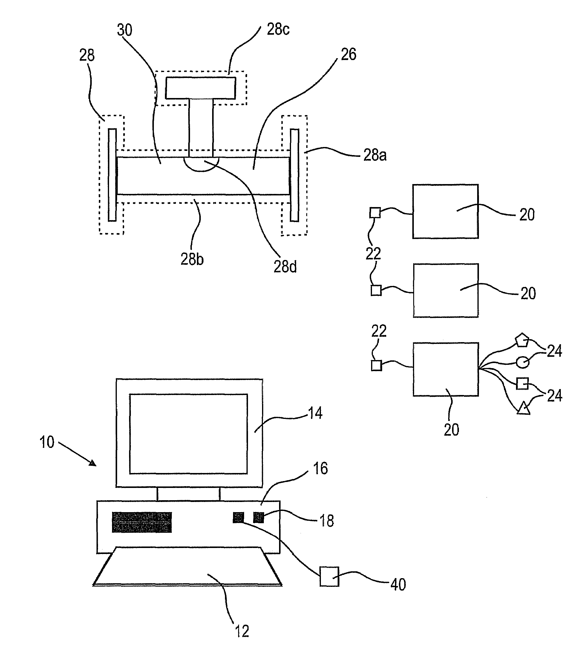
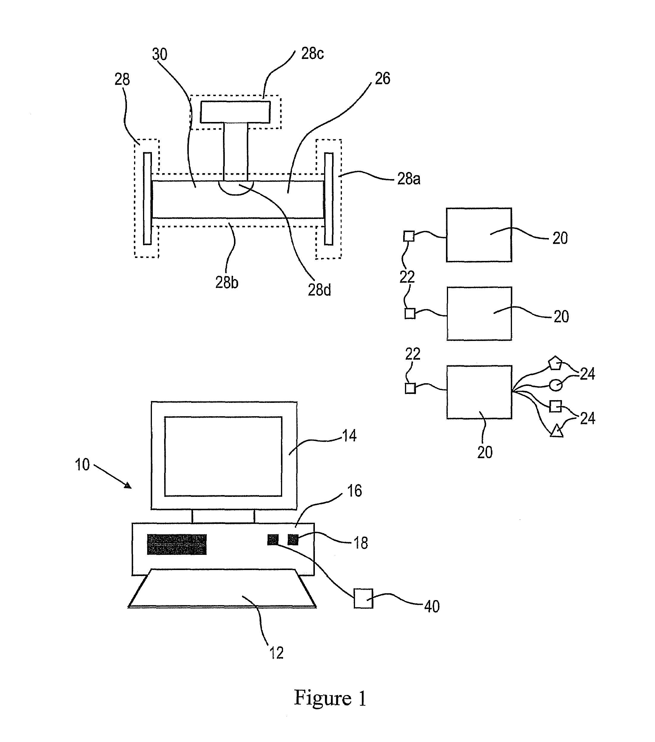
[0059]FIG. 1 shows an apparatus 10 of the invention with an input device 12 (preferably a commercially available keyboard), an output device 14 (preferably a commercially available monitor), a data processing unit 16 (preferably a commercially available computer) comprising the connections or interfaces 18 for connecting the test instruments 20. Beside a usual PC, the use of a notebook or even of a handheld may be envisaged as long as they are capable of performing the necessary computing operations. The output instrument 14 must not necessarily have an imaging output display, in particular cases, numerical output may suffice.

[0060]Primarily, any suitable test instrument can be used as the test instrument 20 for performing non-destructive inspections. As already discussed, the reader is referred to ultrasonic test instruments by way of example. These instruments comprise a connection terminal 22 for connection to a data processing unit 16. It thereby only matters that the various te...


PUM

PropertyMeasurementUnit
frequencyaaaaaaaaaa
insonification angleaaaaaaaaaa

Abstract

The invention relates to a device (10), for the preparation, execution and evaluation of a non-destructive analysis with one or more suitable analysis devices (20) of any type. The device (10) includes an input device (12), an output device (14), a data store, a data processing unit (16), an interface (18) for connection of the analysis device (14), by means of which data may be transmitted in both directions and a standardised data processing programme. It is possible to generate an analysis flow scheme, by means of the data processing programme, whereby an analysis object (26) can be defined, various analysis regions (28) of the analysis object (26) can be determined, a particular analysis device (20) can be selected, analytically-relevant parameters can be selected and determined for the selected analytical device (20), the type of visualisation and the analysis of the measured analytical values can be determined and the obtained analytical results can be archived and stored.

Description

TECHNICAL FIELD OF INVENTION[0001]The present invention pertains to an apparatus for preparing, performing and evaluating a non-destructive inspection. The invention is for example suited for ultrasonic, X-ray or thermography inspection methods.BRIEF DESCRIPTION OF RELATED ART[0002]Non-destructive material inspection serves to detect defects (such as cracks, bubbles, pores, inclusions, and so on), to determine coatings, inner walls and wall thicknesses and to control imposed material properties without compromising the usability of the component. This makes complete inspection of individual parts possible, thus allowing for more reliable evidence as compared to sample inspection. In ultrasonic inspection, ultrasonic waves propagate in a straight line in the frequency range of from about 100 kHz to 25 MHz in solid bodies and are reflected at the interfaces. In the transmission technique, the test piece is interposed between the sound transmitter and the receiver. The sound waves trav...

Claims


Application Information

Patent Timeline
Patent Type & Authority Patents(United States)
IPC IPC(8): G01R31/00G06F19/00G01N29/06G01N29/34G01N29/36G01S7/52
CPCG01N29/0609G01N29/34G01N29/36G01N2291/02827
Inventor KIRCHNER, BERND
Owner GE INSPECTION TECH LP
Learn More