
Composite structural part comprising pyrotechnic detonating rupture means

a technology of composite structural components and pyrotechnic detonation means, which is applied in the direction of cosmonautic components, functional valve types, weapons, etc., can solve the problems of increasing complexity and the time taken to mount said equipment and payload in the launcher

Inactive Publication Date: 2009-04-07
EADS SPACE TRANSPORTATION
View PDF7 Cites 13 Cited by
  • Summary
  • Abstract
  • Description
  • Claims
  • Application Information

AI Technical Summary

Benefits of technology

[0016]able to damp the detonation shock propagating to the free end of said first part when said pyrotechnic separation means are detonated.
[0017]Thus, according to the invention, said damping means are incorporated into said composite structural component, just as are said pyrotechnic separation means. As a result, the detonating shock is damped at source and there is no longer any need to position a plurality of dampers near the equipment and near the payload. In addition, the effectiveness of the damping means is high because the amplitude of the shock has not yet been diminished when the shock reaches said damping means.
[0018]It will also be noted that, from an industrial standpoint, the present invention is advantageous because it makes it possible to obtain a single composite component incorporating the pyrotechnic separation means and the means of damping the detonation shock.
[0020]Thus, said damping means not only damp the detonation shock but also stiffen the means of assembly between said first and second parts of said composite structural component. They therefore simultaneously form a barrier to the detonation waves and a mechanical connection between said first and second parts.

Problems solved by technology

It will be noted that the arrangement of such a plurality of discrete attenuation means increases the complexity and the time taken to mount said equipment and the payload in the launcher.

Method used


Image

  • Composite structural part comprising pyrotechnic detonating rupture means
  • Composite structural part comprising pyrotechnic detonating rupture means
  • Composite structural part comprising pyrotechnic detonating rupture means

Examples


Embodiment Construction

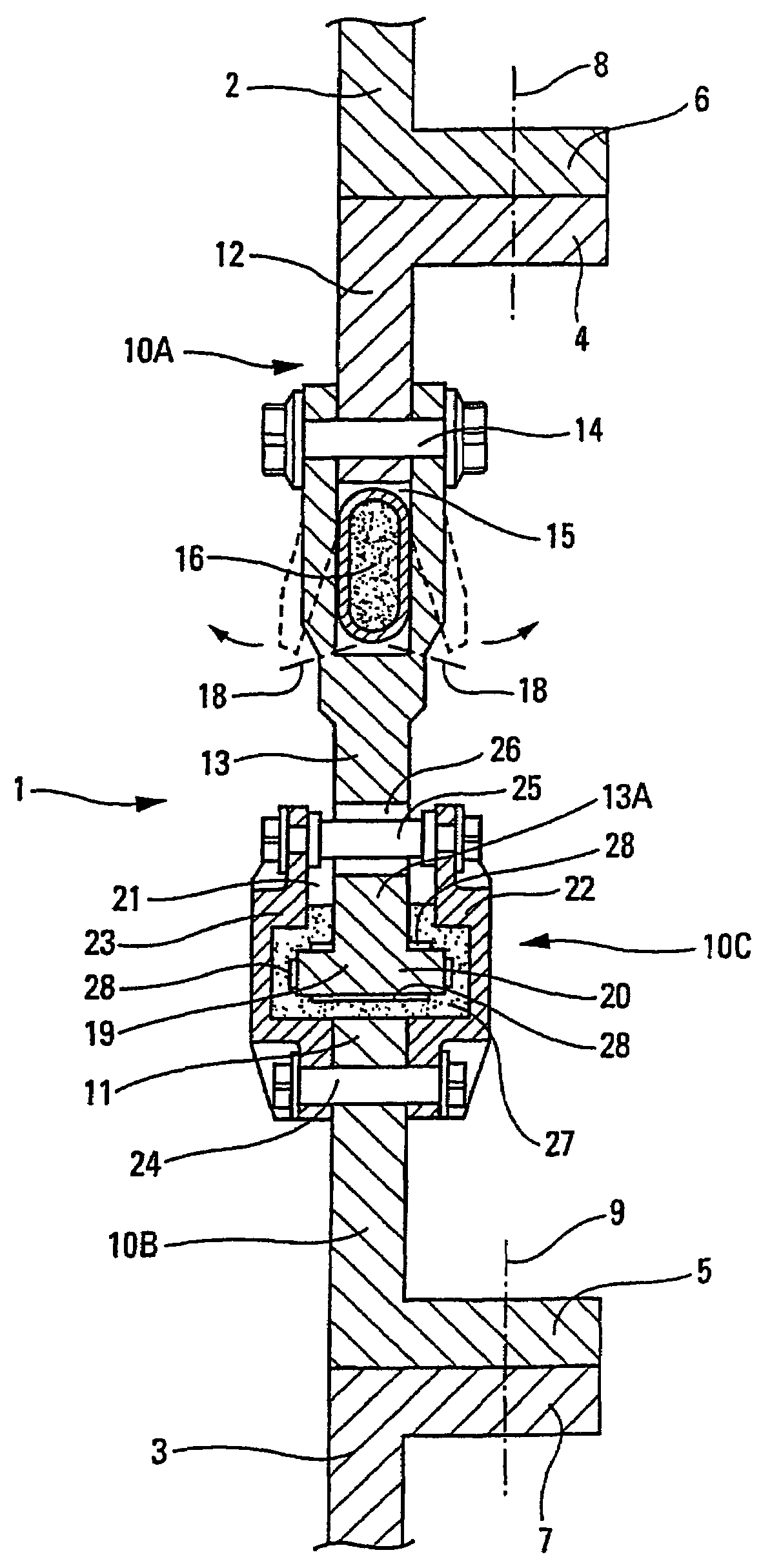
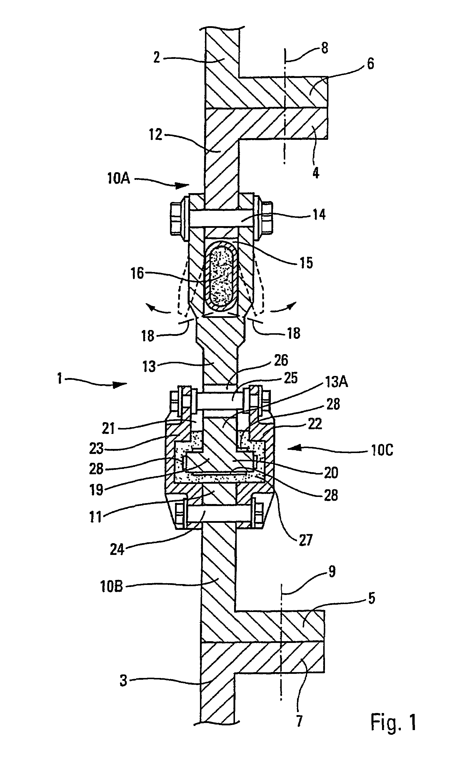
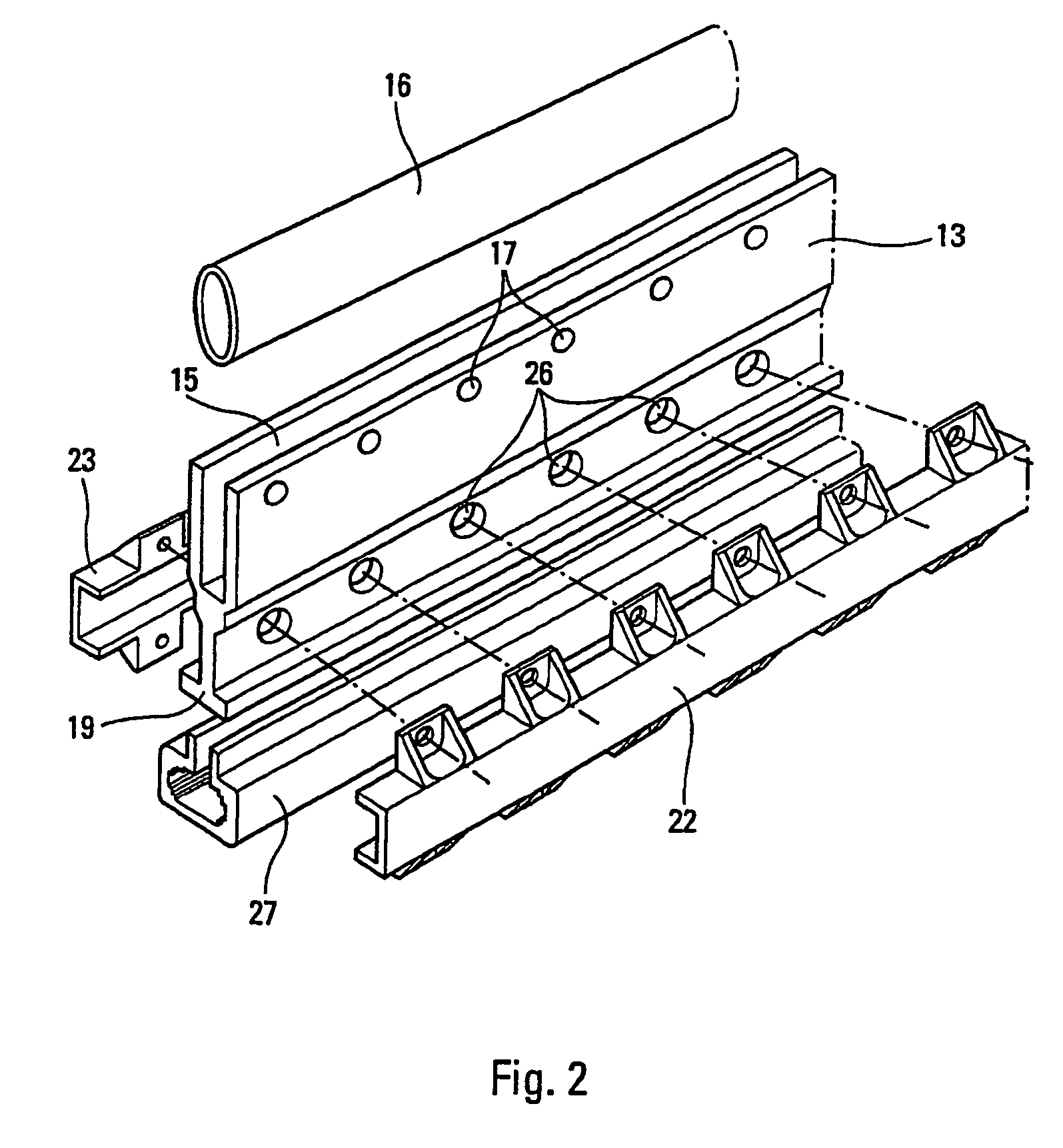
[0028]The pyrotechnically ruptureable composite structural component 1 shown by way of example in FIG. 1 secures elements 2 and 3 of a mechanical structure (not otherwise depicted) between which it is located. For this purpose, the structural component 1, for example made of light alloy, is provided at its ends with flanges 4 and 5 able to collaborate, respectively, with a flange 6 of the element 2 and with a flange 7 of the element 3 and clamping means 8 and 9 (depicted only by way of their axes in FIG. 1) securing the flanges 4 and 6 and the flanges 5 and 7, respectively.

[0029]The structural component 1 consists of a first part 10A, of a second part 10B and of means 10C of assembling said first and second parts.

[0030]The second part 10B bears the flange 5 and is therefore connected to the element 3. At the opposite end to the flange 5, the second part 10B has a free end 11, facing toward the first part 10A.

[0031]For its part, the first part 10A comprises two elements 12 and 13 fix...


PUM

PropertyMeasurementUnit
Forceaaaaaaaaaa
Shapeaaaaaaaaaa
Mechanical propertiesaaaaaaaaaa

Abstract

A pyrotechnically-ruptureable composite structural component, intended to transmit forces between first and second structural elements, has an elongate pyrotechnic detonation separation component incorporated in the structural component for breaking the structural component and separating the first and second elements. The structural component has a first part in which the pyrotechnic separation component is incorporated and which is able to be connected to the first element, and a second part that connects to the second element. The first and second parts are rigidly assembled via their free ends, which are the opposite ends to the first and second elements respectively. The rigid assembly has a damper arranged between the free ends of the first and second elements so as to damp a detonation shock propagating to the free end of the first part when the pyrotechnic separation component is detonated.

Description

FIELD OF THE INVENTION[0001]The present invention relates to a pyrotechnic detonating ruptureable composite structural component quite particularly, although not exclusively, suited for use in space launchers. It will be described hereinafter more particularly in the latter application.BACKGROUND OF THE RELATED ART[0002]It is known that certain elements of space launchers, such as adjacent stages, are mechanically joined together by a composite structural component intended to transmit mechanical forces between said elements as necessary and provided with pyrotechnic detonation separation means incorporated in said structural component and able to break it along the straight or curved line of separation when said elements have to be separated from one another. Similar composite structural components also allow the satellite bearing structures to be severed on board launchers.[0003]At the moment of rupture of such a structural component, that is to say at the moment of separation of ...

Claims


Application Information

Patent Timeline
IPC IPC(8): B64D1/04B64G1/64F15B15/19F42B15/38
CPCB64G1/645F42B15/38B64G1/641Y10T83/8863Y10T137/1647B64G1/642B64G1/6455B64G1/6425
Inventor KISTER, THOMAS
Owner EADS SPACE TRANSPORTATION
Learn More