

Energy harvesting technique to support remote wireless MEMS RF sensors
a technology of energy harvesting and remote sensing, applied in the field of remote sensing, can solve the problems of limited data available, low power consumption, and high cost of models, and achieve the effect of increasing the functionality of wireless devices and increasing the amount of power harvested
- Summary
- Abstract
- Description
- Claims
- Application Information
AI Technical Summary
Benefits of technology
Problems solved by technology
Method used
Image

Examples
Embodiment Construction
[0018]Preferred embodiments of the present invention are illustrated in the figures like numerals being used to refer to like and corresponding parts of the various drawings.
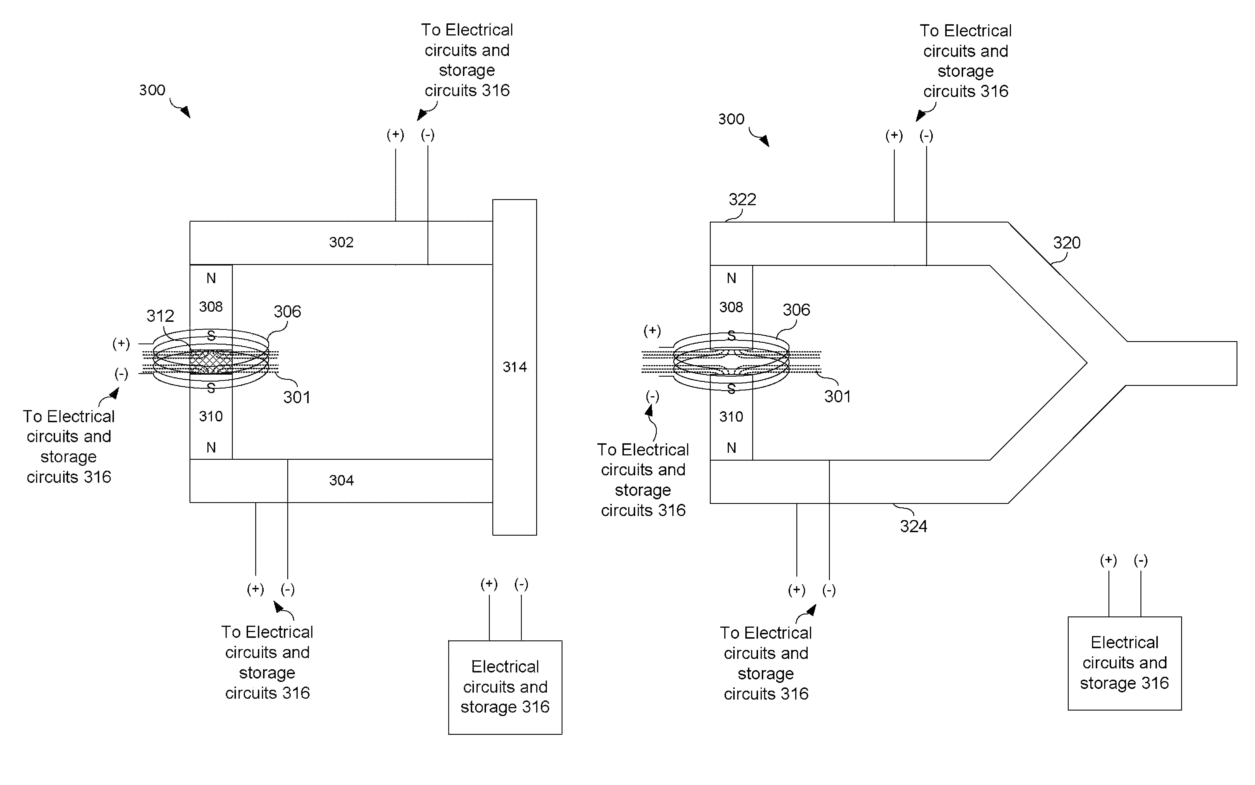
[0019]Current wireless remote sensors for modeling, prognostics, diagnostics or identification require battery assisted power sources in order to wirelessly transmit data because insufficient power is harvested through existing designs. Embodiments of the present invention combine Piezoelectric (PZT) technique and Faraday's law in electric generation by crossing high dense magnetic flux through the coil to generate sufficient charges for storage and operation need. By coupling two form magnets, or electromagnets, with the same pole (N) or (S), with a thin non-conductive layer a high magnetic flux density field can be generated. These magnets may be held in place with a mechanical mount made from PZT materials. Thus vibrational energy applied to the PZT materials and magnets can be translated into electrical ener...
PUM
 Abstract
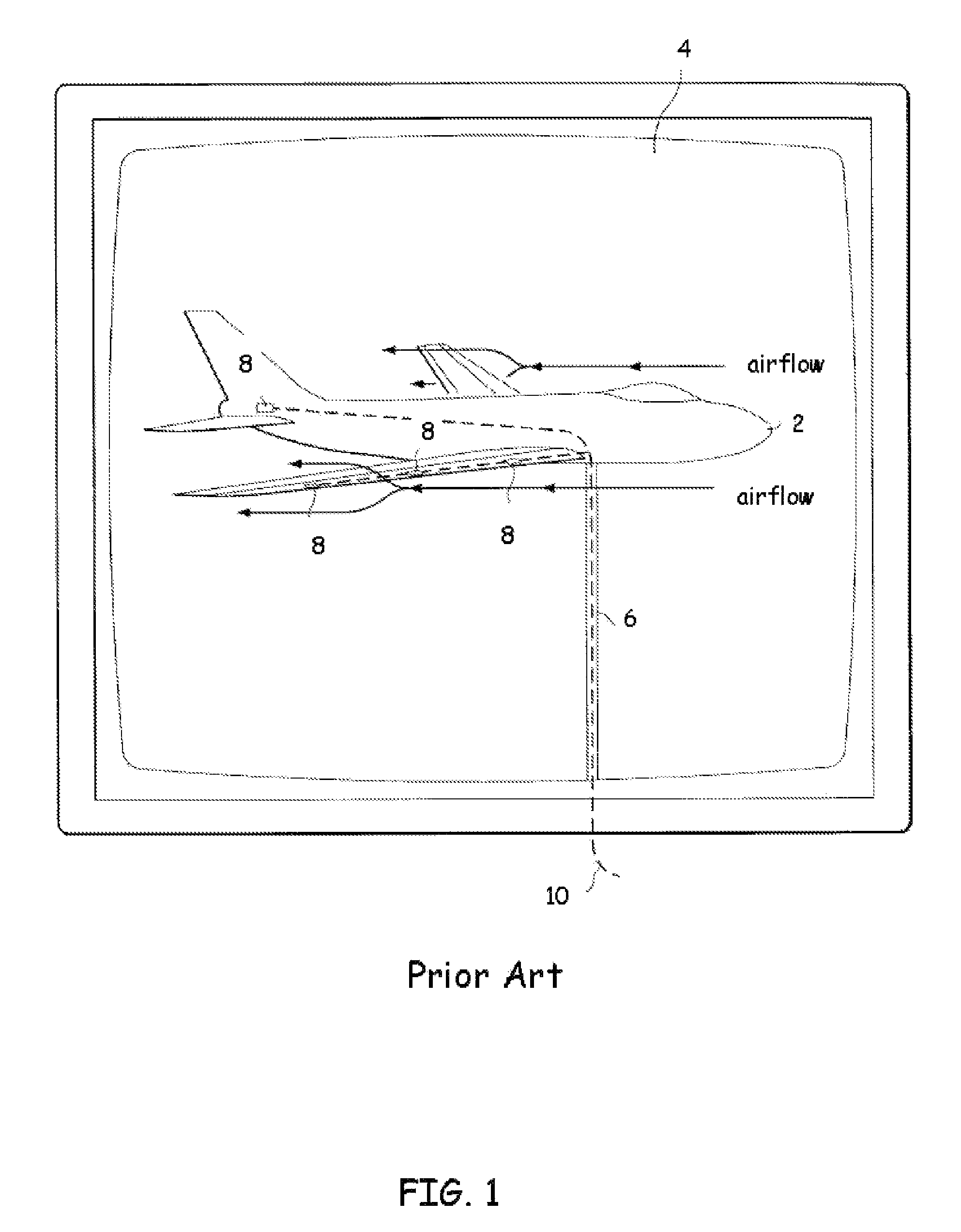
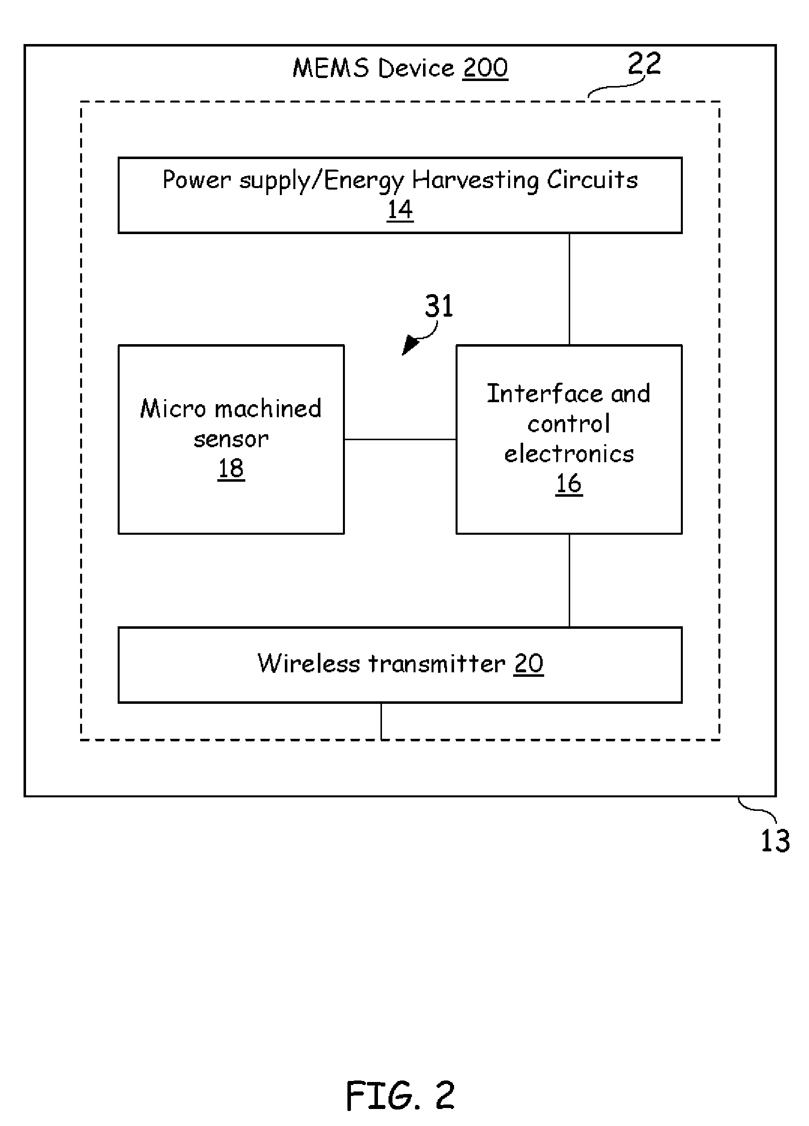
Description
Claims
Application Information