Hydraulic drive system

a technology of hydraulic drive and drive shaft, which is applied in the direction of fluid coupling, servomotor, coupling, etc., can solve the problems of inflexibility in implementing different control strategies, loss of energy, and inefficient valve systems in terms of energy dissipation across valves

Inactive Publication Date: 2009-04-14
CONCENTRIC ROCKFORD
View PDF150 Cites 36 Cited by
  • Summary
  • Abstract
  • Description
  • Claims
  • Application Information

AI Technical Summary

Benefits of technology

[0006]In order to reduce the operating forces required by a valve, is known to utilize a servo valve in which a pilot operation is used to control the fluid flow. In such an arrangement, a pivot valve balances a pair of pilot flows and can be moved to increase one flow and decrease the other. The change in flows is used to move a control valve and operate the hydraulic device. The force required to move the pilot valve is less than that required for the control valve and therefore enhanced control is obtained. However, there is a continuous flow at high pressure through the pilot valve resulting in significant losses. The control valve itself also suffers deficiencies of energy loss due to metering flow across restrictive ports and therefore, although it offers enhanced control, the energy losses are significant.

Problems solved by technology

Such valve systems are relatively inefficient in terms of the energy dissipated across the valve.
In an open centre arrangement, careful manufacture of the valve is required in order to obtain the transition between the zero flow and full flow whilst retaining control of the load and metering of the flow across the valve causes loss of energy.
As such, the valves tend to be specialized and do not offer flexibility in implementing different control strategies.
Most significantly, since the control is achieved by metering flow across an orifice there is inherently significant energy loss when controlling fluid flow.
Because the control valve is typically a one piece spool, a similar restricted port is presented to the exhaust flow and results in a significant energy loss.
However, there is a continuous flow at high pressure through the pilot valve resulting in significant losses.
The control valve itself also suffers deficiencies of energy loss due to metering flow across restrictive ports and therefore, although it offers enhanced control, the energy losses are significant.

Method used


Image

  • Hydraulic drive system
  • Hydraulic drive system
  • Hydraulic drive system

Examples


Embodiment Construction

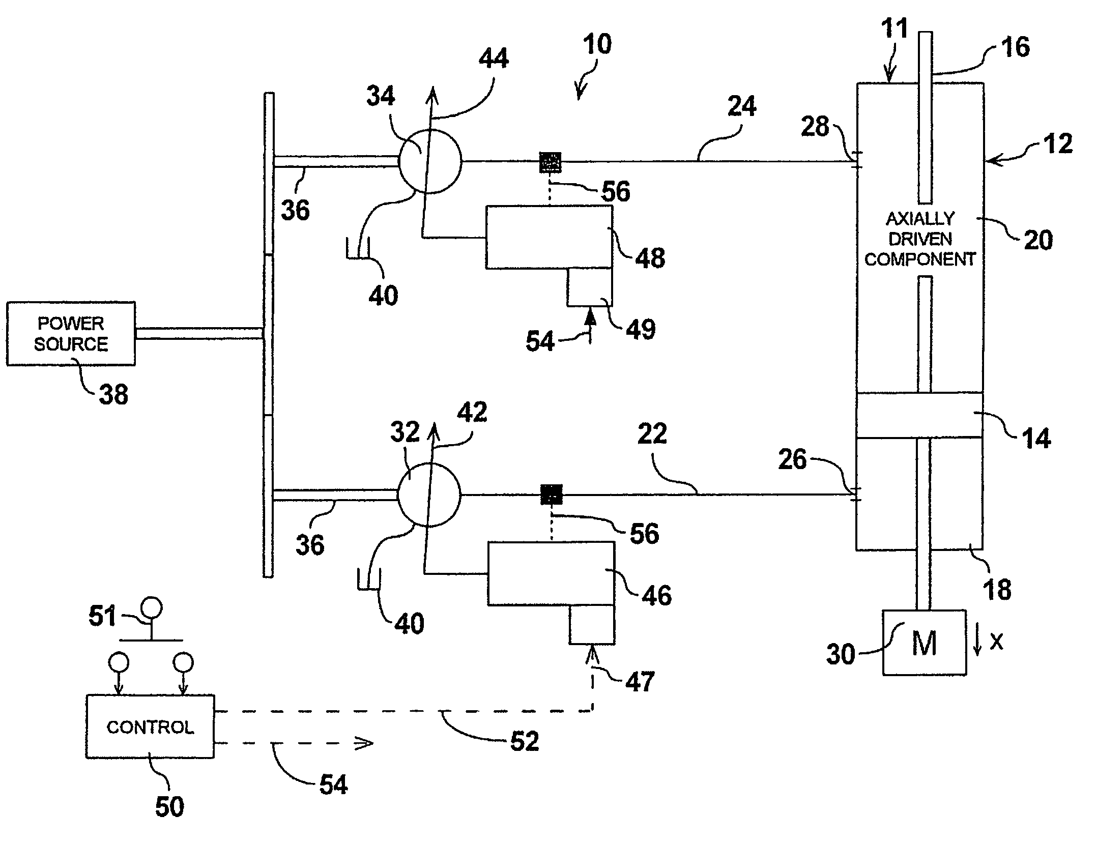
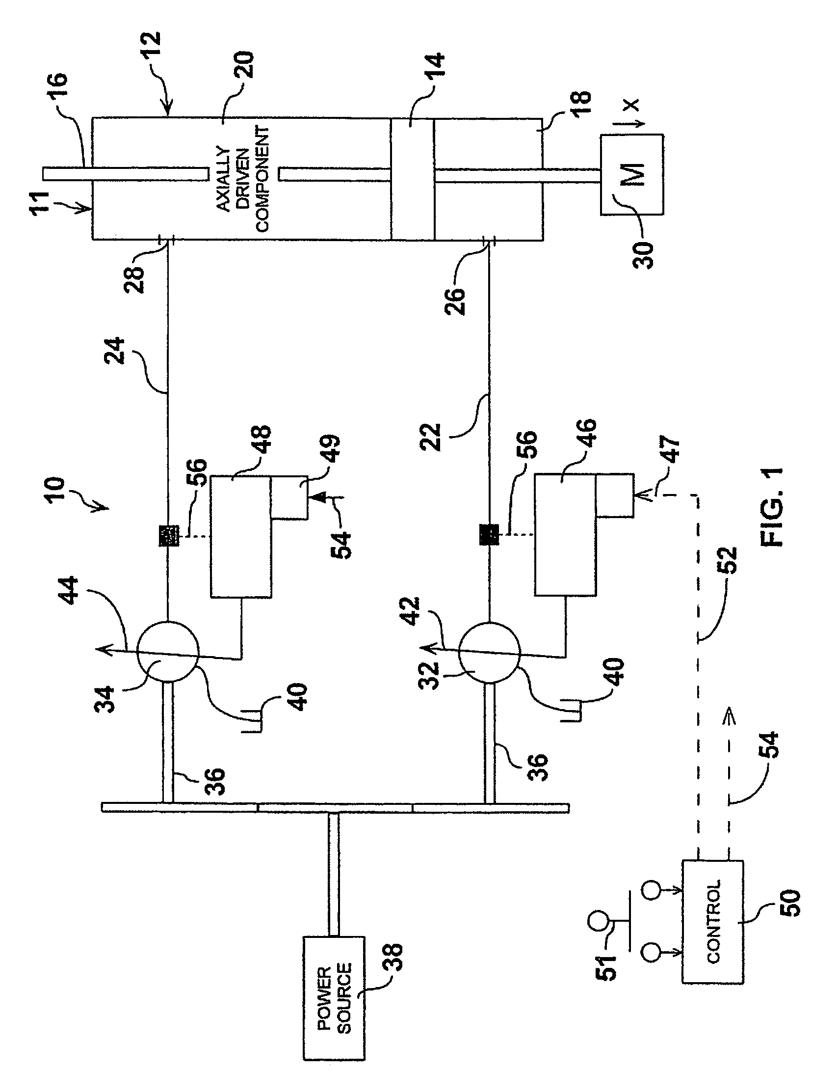
[0020]Referring therefore to FIG. 1, a hydraulic drive system 10 includes an actuator 11 having a cylinder 12 with a piston 14 supported within the cylinder 12. The piston 14 is connected to a piston rod 16 that extends from opposite ends of the cylinder 12. The piston 14 subdivides the cylinder 12 into chambers 18 and 20 which are connected to supply lines 22, 24 by ports 26, 28 respectively. The rod 16 is connected to a load 30 shown schematically as a horizontal sliding mass.

[0021]The supply lines 22, 24 are connected to the outlets of a pair of variable capacity hydraulic machines 32, 34. The machines 32, 34 are typically a swashplate device in which the angle of inclination of a swash plate determines the capacity of the machine. Alternatively, the devices could be a radial piston pump in which variation in the eccentricity of the control ring determines the capacity of the pump. The machines 32, 34 are reversible to permit each to operate in a pumping mode or motoring mode. Th...


PUM


Abstract

A hydraulic drive system for an actuator uses a pair of pressure compensated hydraulic machines to control flow to and from the drive chambers of the actuator by varying the controlled pressure of one of the machines. The machines are mechanically coupled to permit energy recovery and charge an accumulator to store supplies energy. The drive system may be combined with other services including a transmission for incorporation in a vehicle. The transmission uses a pressure compensated supply and torque control of the wheels.

Description

[0001]This patent application claims the benefit of, under Title 35, United States Code, Section 119(e), U.S. Provisional Application No. 60 / 632,178 filed on Dec. 1, 2004, U.S. Provisional Application No. 60 / 632,176 filed on Dec. 1, 2004 and U.S. Provisional Application No. 60 / 677,103 filed on May 3, 2005.FIELD OF THE INVENTION[0002]The present invention relates to energy transmission systems and more particularly to such systems utilizing hydraulic fluid as an energy transfer medium.SUMMARY OF THE INVENTION[0003]It is well-known to transfer energy from a source such as a motor or internal combustion engine to a load through the intermediary of hydraulic drive system. Such systems will typically have a pump driven by the source and a motor connected to the load. By adjusting the hydraulic flow between the pump and the motor it is possible to impart movement to the load, maintain it in a fixed position and otherwise influence its disposition.[0004]The control of fluid flow is typical...

Claims


Application Information

Patent Timeline
Patent Type & Authority Patents(United States)
IPC IPC(8): F15B11/00E02F9/22
CPCF15B1/024F15B7/001F15B7/005F15B11/17F15B21/14F15B2211/20523F15B2211/20546F15B2211/20561F15B2211/20569F15B2211/20576F15B2211/212F15B2211/27F15B2211/6303F15B2211/633F15B2211/6333F15B2211/6652F15B2211/6653F15B2211/6656F15B2211/7053F15B2211/7054F15B2211/88Y02T10/62F15B9/00F15B1/02
Inventor KADLICKO, GEORGE
Owner CONCENTRIC ROCKFORD
Why Eureka
Try Eureka