

Infra-red emitting decoy flare
a decoy flare and infrared technology, applied in the field of infrared (ir) emitting decoy flares, can solve the problems of undesirable illumination of the target by the visible emission of decoy flares, and the emission of visible and ultra violet (uv) emission of burning phosphorous containing incendiary pastes
- Summary
- Abstract
- Description
- Claims
- Application Information
AI Technical Summary
Benefits of technology
Problems solved by technology
Method used
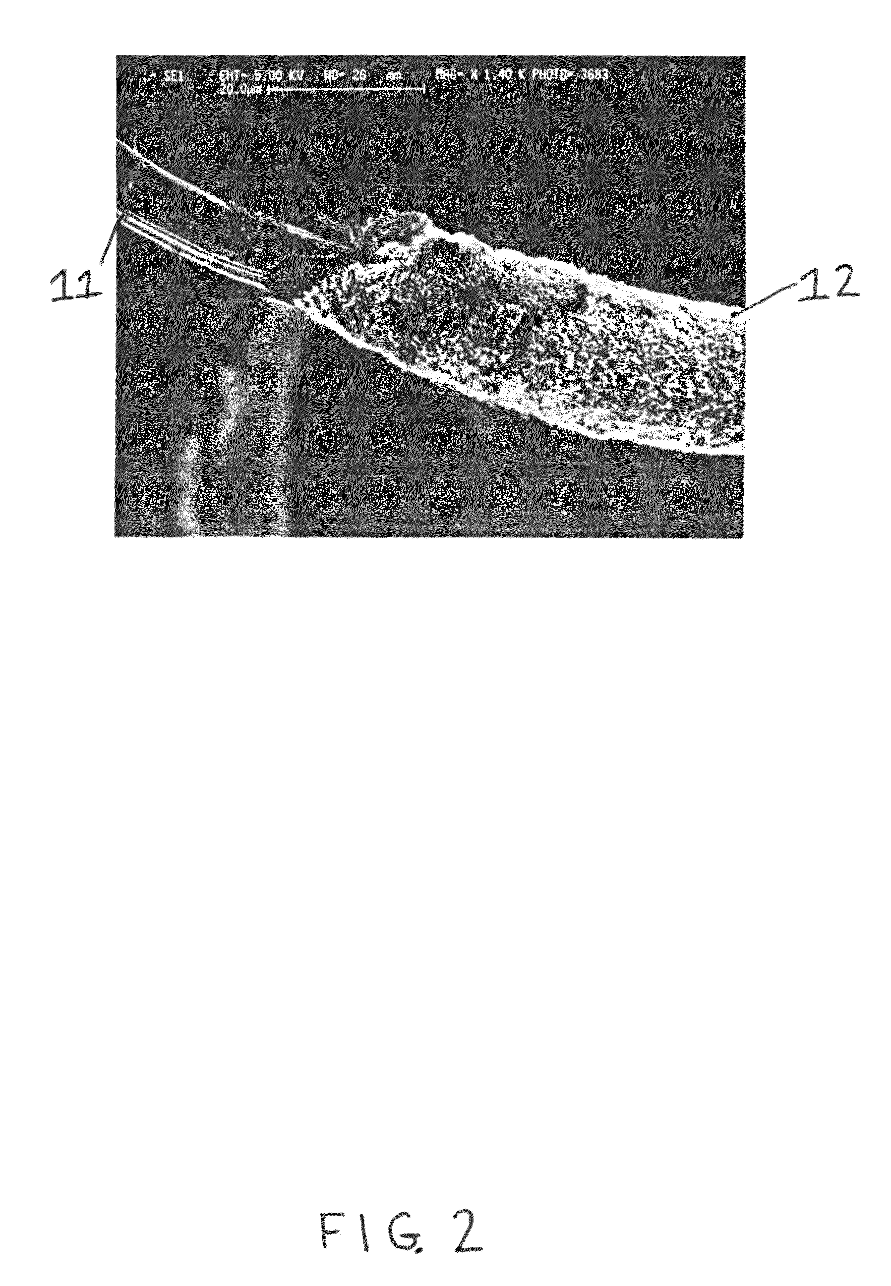
Image

Examples
Embodiment Construction
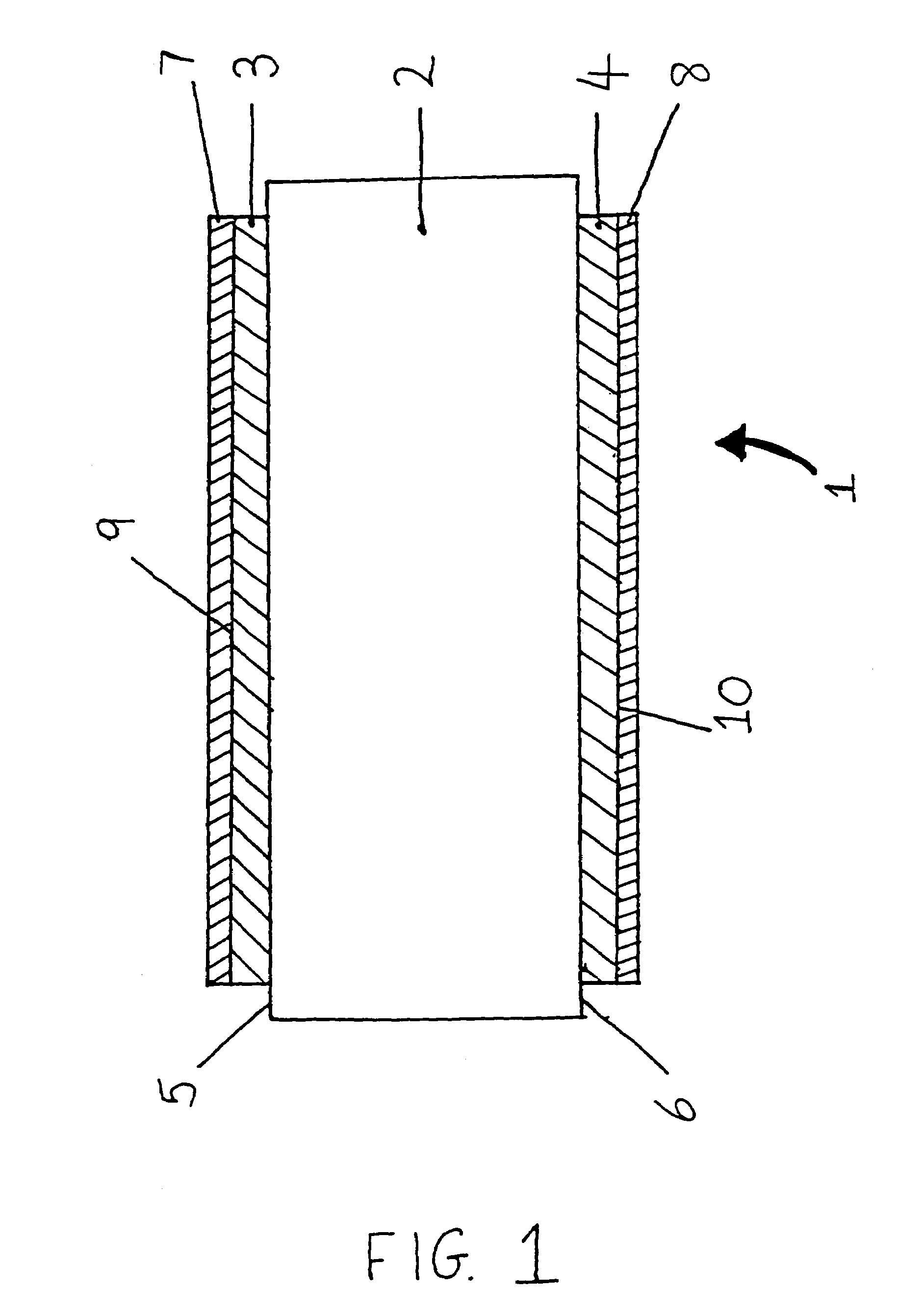
[0036]Referring now to FIG. 1, combustible material flake 1 consists of a carbonised viscose rayon substrate 2 having combustible layers 3, 4 each consisting of approximately 40 microns thick magnesium, vapour deposited onto substantially all of the surface of the respective faces 5, 6 thereof. Further layers 7, 8 of titanium as a protective coat are vapour deposited to a thickness of approximately 0.5 microns onto the exposed surfaces 9, 10 of the combustible layer 3, 4.
[0037]The substrate 2 is formed from a 2.5 cm×10 cm×150 micron, 110 g / m3 fibre containing viscose rayon tape. The tape is then carbonised in the presence of a copper salt activating agent and a potassium salt oxidant precursor at around 1200° C. using a conventional pyrolysis carbonisation process comprising four stages:
[0038]precarbonisation, where physically adsorbed solvent, water or monomers are removed;
[0039]carbonisation (between 300 and 500° C.), during which oxygen, nitrogen and halogens are removed and conj...
PUM
| Property | Measurement | Unit |
|---|---|---|
| Length | aaaaa | aaaaa |
| Thickness | aaaaa | aaaaa |
| Thickness | aaaaa | aaaaa |
Abstract
Description
Claims
Application Information