Optical sensor and methods for measuring molecular binding interactions

a molecular binding and optical sensor technology, applied in the field of optical sensors, can solve the problems of high cost of spr sensors, impracticality of many applications, high cost of resonant mirror systems,

Inactive Publication Date: 2009-04-14
NISSHA PRINTING COMPANY
View PDF7 Cites 26 Cited by
  • Summary
  • Abstract
  • Description
  • Claims
  • Application Information

AI Technical Summary

Problems solved by technology

These SPR sensors are typically very expensive.
As a result, the technique is impractical for many applications.
Like SPR sensors, resonant mirror systems are expensive and impractical for many applications.
In addition to the optical biosensors discussed above, scientists perform kinetic binding measurements using other separations methods on solid surfaces combined with expensive detection methods (such as capillary liquid chromatography / mass spectrometry) or solution-phase assays.
These methods suffer from disadvantages of cost, the need for expertise, imprecision and other factors.

Method used


Image

  • Optical sensor and methods for measuring molecular binding interactions
  • Optical sensor and methods for measuring molecular binding interactions
  • Optical sensor and methods for measuring molecular binding interactions

Examples


example demonstrating

Chemical Features of Preferred Embodiments

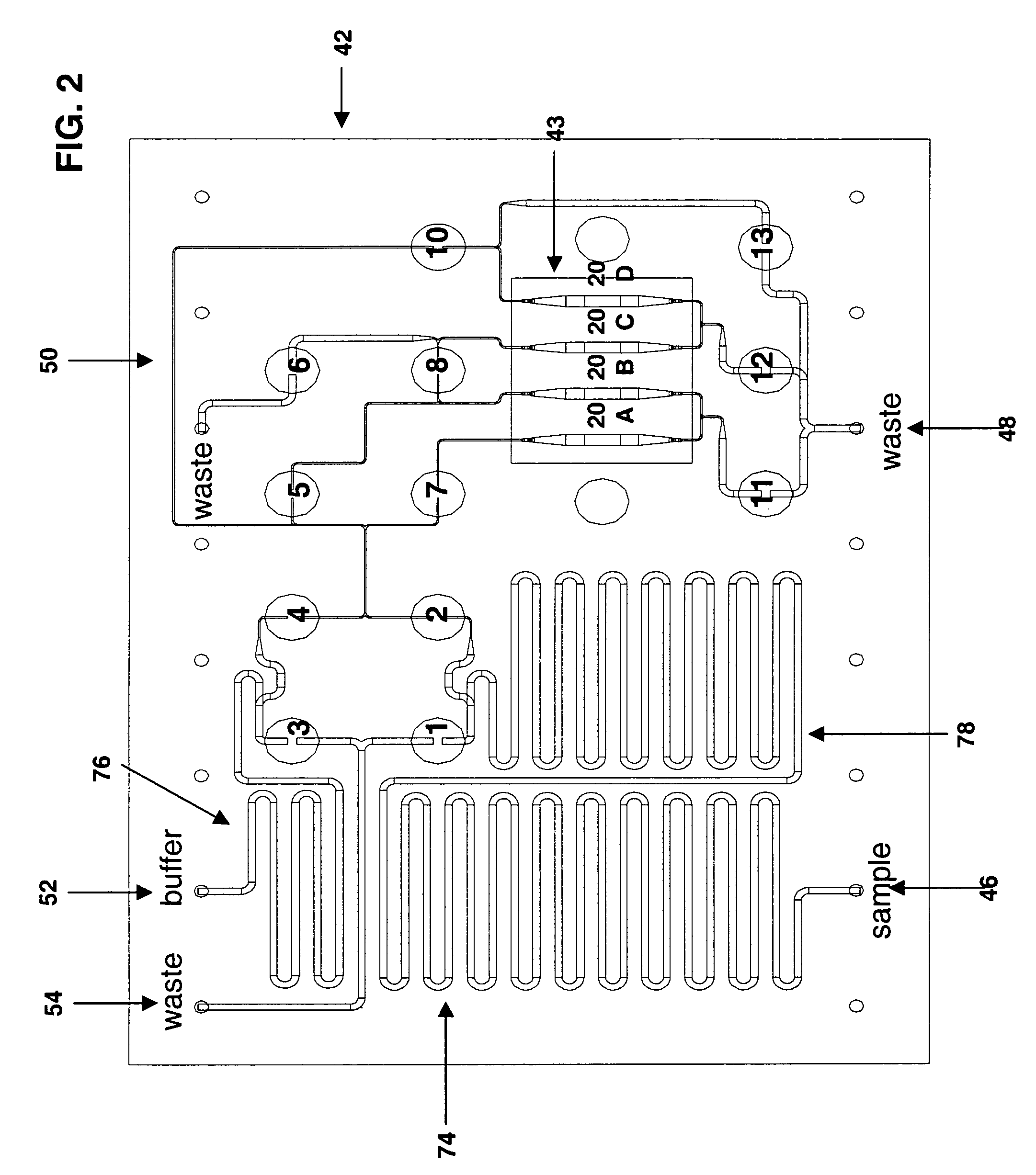
[0042]In addition to providing the key component for the optical measurement subsystem, the porous section observation regions 20A, B, C and D also serve as three-dimensional scaffolds to immobilize specific molecules. The regions provide a very large surface area in the form of cylindrical walls of pores 90. Ligand molecules are attached, or bound, to the pore walls 90 by the use of specific linker molecules. The linker molecules are attached to the pore walls by the use of surface chemistry, and the ligand molecules are then attached to the linker molecules.

[0043]FIGS. 9A-9F show a specific set of molecular interactions involved in an example of an application of the present invention. FIGS. 9A and 9B show steps a) and b) of a preferred method for immobilizing ligand protein molecules to the walls of pores 90. Steps a) and b) preferably are performed in a laboratory independent of the device shown in FIG. 1 and steps 9C-9F take place withi...


PUM

PropertyMeasurementUnit
depthsaaaaaaaaaa
depthsaaaaaaaaaa
total lengthaaaaaaaaaa

Abstract

Methods and devices for the measurement of molecular binding interactions. Preferred embodiments provide real-time measurements of kinetic binding and disassociation of molecules including binding and disassociation of protein molecules with other protein molecules and with other molecules. In preferred embodiments ligands are immobilized within pores of a porous silicon interaction region produced in a silicon substrate, after which analytes suspended in a fluid are flowed over the porous silicon region. Binding reactions occur when analyte molecules diffuse closely enough to the ligands to become bound. Preferably the binding and subsequent disassociation reactions are observed utilizing a white light source and thin film interference techniques with spectrometers arranged to detect changes in indices of refraction in the region where the binding and disassociation reactions occur. In preferred embodiments both ligands and analytes are delivered by computer controlled robotic fluid flow control techniques to the porous silicon interaction regions through microfluidic flow channels.

Description

[0001]This application claims the benefit of provisional patent application Ser. No. 60 / 399,524 filed Jul. 30, 2002. This invention relates to optical sensors and in particular to optical biosensors.BACKGROUND OF THE INVENTION[0002]The prior art includes a wide variety of optical sensors. An optical biosensor is an optical sensor that incorporates a biological sensing element. In recent years optical biosensors have become widely used for sensitive molecular binding measurements.SURFACE PLASMON RESONANCE[0003]An optical biosensor technique that has gained increasing importance over the last decade is the surface plasmon resonance (SPR) technique. This technique involves the measurement of light reflected into a narrow range of angles from a front side of a very thin metal film producing changes in an evanescent wave that penetrates the metal film. Ligands and analytes are located in the region of the evanescent wave on the backside of the metal film. Binding and disassociation actio...

Claims


Application Information

Patent Timeline
Patent Type & Authority Patents(United States)
IPC IPC(8): C12M1/34B01L3/00G01N21/84G01N33/552G01N35/00
CPCB01L3/5023B01L3/502746B01L3/502753G01N21/84G01N33/552B01L3/5025B01L3/502715B01L2300/0654B01L2300/0816B01L2300/0867B01L2400/0487B01L2400/0655G01N2035/0097G01N21/77G01N2021/752G01N2021/755G01N2021/757G01N2021/758G01N2021/7779G01N2021/7796Y10S435/808
Inventor MARTIN, PETERDANCIL, KEIKI-PUAMORSELL, ARTHUR LEETIGLI, HUS
Owner NISSHA PRINTING COMPANY
Why Eureka
Try Eureka