Scanning x-ray apparatus

a scanning x-ray and apparatus technology, applied in the field of scanning x-ray apparatus, can solve the problems of wasting x-ray energy and requiring a relatively higher x-ray generation capacity

Inactive Publication Date: 2009-04-14
LODOX SYST
View PDF14 Cites 7 Cited by
  • Summary
  • Abstract
  • Description
  • Claims
  • Application Information

AI Technical Summary

Benefits of technology

[0011]Preferably, the control system is arranged to combine the output signals of groups comprising greater numbers of pixels as the collimator is adjusted to increase the width of the imaging beam in the scanning direction, thereby to increase the contrast resolution of the image signals for a given spatial resolution.
[0021]The method may comprise combining the output signals of groups comprising greater numbers of pixels as the collimator is adjusted to increase the width of the imaging beam in the scanning direction, thereby to increase the contrast resolution of the image signals for a given spatial resolution.

Problems solved by technology

This requires the use of a beam limiting device, which is wasteful of x-ray energy and requires a relatively higher x-ray generation capacity than a comparable full field system.

Method used


Image

  • Scanning x-ray apparatus
  • Scanning x-ray apparatus
  • Scanning x-ray apparatus

Examples


Embodiment Construction

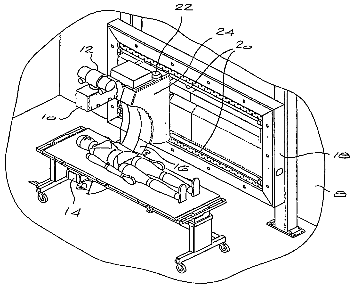
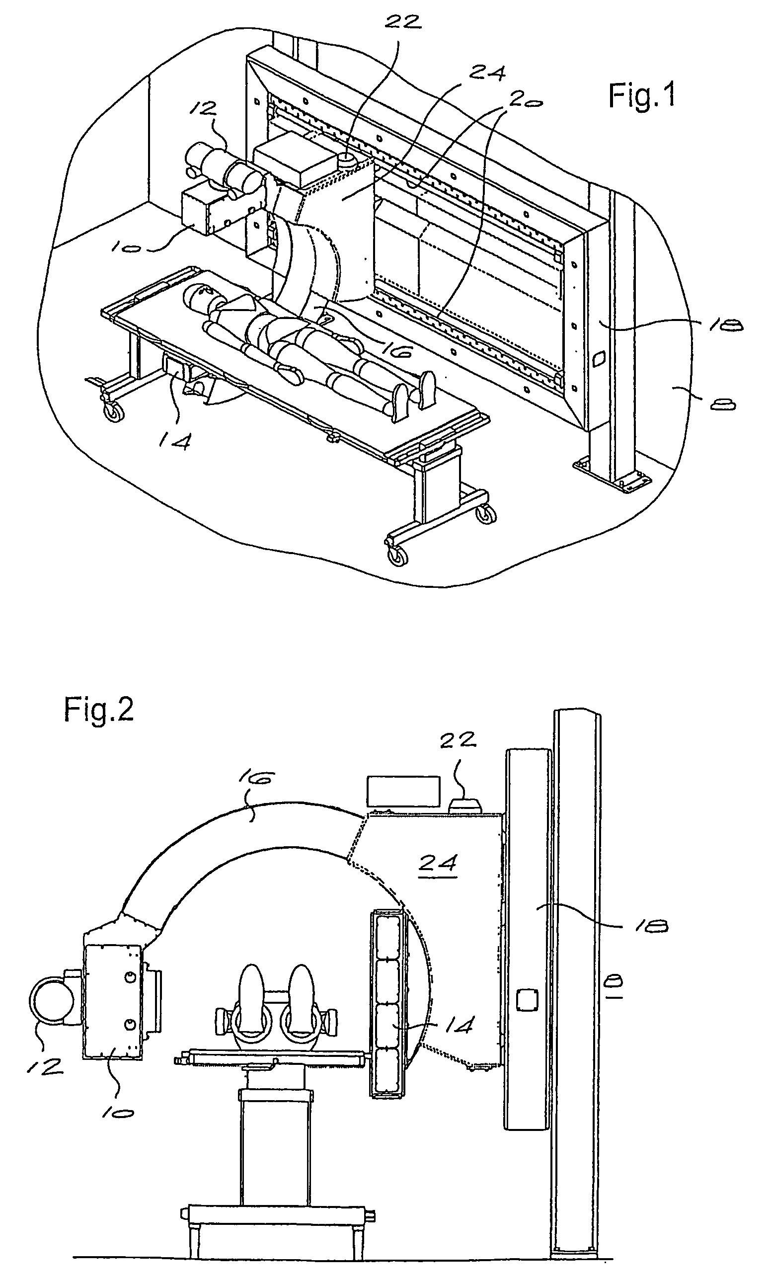
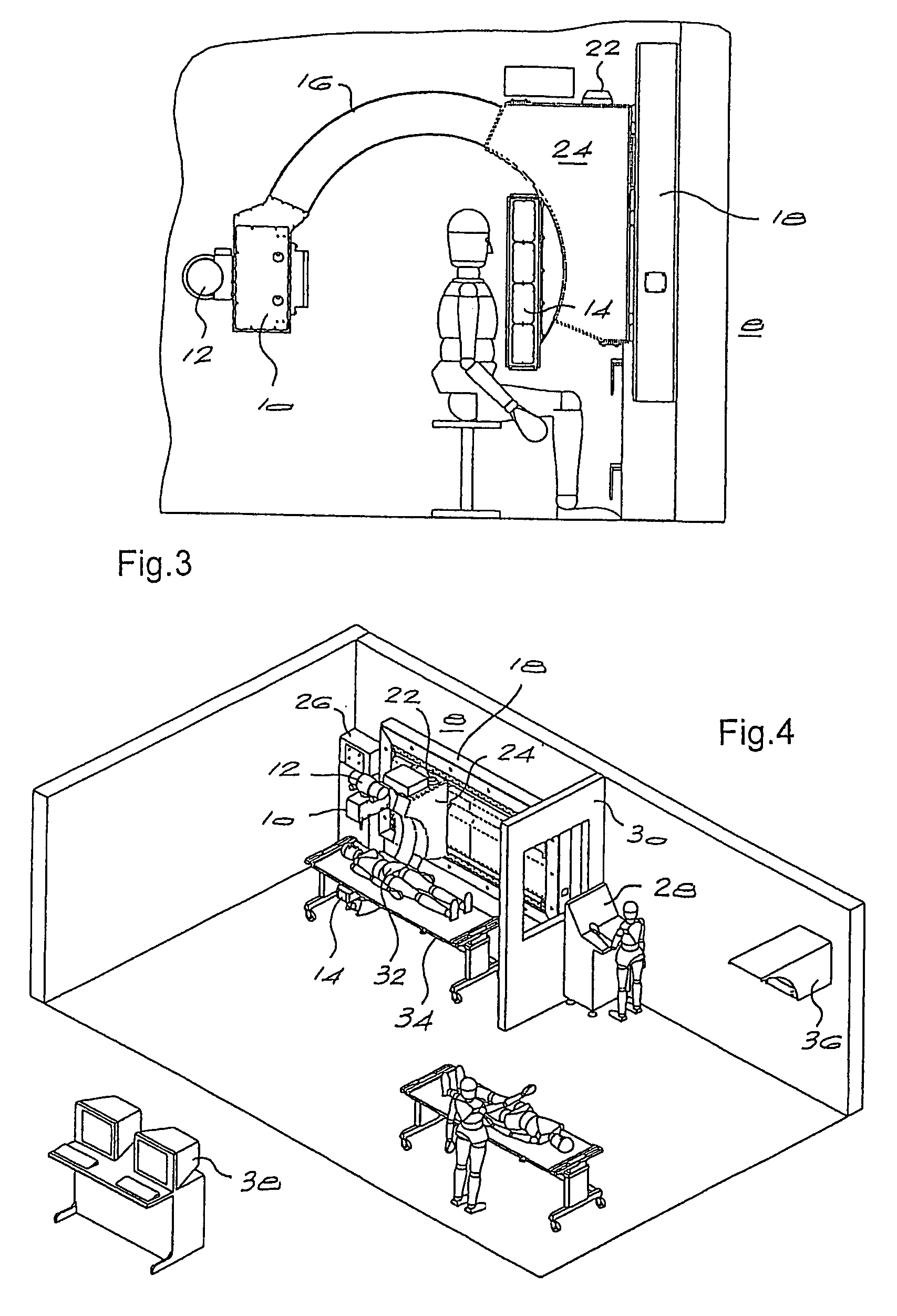
[0040]FIGS. 1 to 3 show three different views of prototype X-ray imaging or scanning apparatus of the invention. The apparatus comprises a head 10 containing an X-ray source 12 which emits a narrow, fanned beam of X-rays towards a detector unit 14. The X-ray source 12 and the detector unit 14 are supported at opposite ends of a curved arm 16 which is generally semi-circular or C-shaped.

[0041]A frame 18 mounted on a wall 8 or another fixed structure defines a pair of rails 20 with which a motorised drive mechanism 22 engages to drive the arm linearly back and forth in a first, axial direction of movement. This corresponds to the direction of scanning in use. In addition, the drive mechanism comprises a housing 24 in which the arm 16 is movable by the drive mechanism in order to cause the X-ray source and the detector to rotate about an axis parallel with the scanning direction of the mechanism.

[0042]A typical application of the imaging apparatus of the invention is in a radiological ...


PUM


Abstract

Linear scanning x-ray apparatus generates a collimated fan beam which is moved together with a detector relative to a subject to generate a composite x-ray image of the subject. An adjustable collimator varies the width of the imaging beam in the scan direction. A control system responds to adjustment of the collimator to combine output signals of groups of two or more pixels in the detector, in order to optimize the contrast resolution of the image signals for a given spatial resolution. The invention provides a collimator for use in the apparatus.

Description

BACKGROUND OF THE INVENTION[0001]This invention relates to imaging apparatus of the kind comprising a radiation source and a detector which are moveable relative to a subject; a collimator for adjusting the effective width of an imaging beam generated by such apparatus; and a method of operating such apparatus.[0002]Imaging apparatus which utilizes an x-ray source and an associated detector is known, in which the x-ray source and detector are moved relative to a subject in a scanning process, in order to generate a composite x-ray image of the subject. Apparatus of this kind is described in International patent application no. WO 00 / 53093, for example. In the apparatus described in the abovementioned patent application, an x-ray source is mounted on one end of a C-shaped arm and emits a low-dose collimated fan beam of x-rays. Mounted on the opposite end of the C-arm is an x-ray detector unit, comprising scintillator arrays optically linked to charge coupled devices (CCDs). An image ...

Claims


Application Information

Patent Timeline
Patent Type & Authority Patents(United States)
IPC IPC(8): G21K1/02G21K1/00A61B6/00A61B6/03A61B6/06G21K1/04
CPCA61B5/0046A61B6/032A61B6/06A61B6/5205G21K1/04
Inventor VERMEULEN, ANDRIES GERHARDUS JOHANNESPOTGIETER, JOHANNES HERMANUSVAN LOOY, PAUL
Owner LODOX SYST
Why Eureka
Try Eureka