Radio-frequency radiocommunication apparatus

a radiocommunication apparatus and radio frequency technology, applied in the direction of reradiation, collapsible antenna means, instruments, etc., can solve the problems of radio interference in the receiver, large manpower, and the inability of conventional radiocommunication apparatuses to transmit/receive radio waves at a level higher, so as to achieve the effect of reducing the size and weight of the transmitting/receiving device and facilitating the change of the transmission route of the radio signal

Inactive Publication Date: 2009-04-14
SHARP KK
View PDF41 Cites 17 Cited by
  • Summary
  • Abstract
  • Description
  • Claims
  • Application Information

AI Technical Summary

Benefits of technology

[0038]When the milli-wave band is utilized, for example, the size and the weight of the transmitting / receiving device can be reduced. Accordingly, the transmitting / receiving device can be integrated with a directional antenna. According to the present invention, the directional antenna is contained in the dielectric case, and the direction of the directional antenna thus can be changed by changing the direction of the dielectric case. Thus, the directional antenna can be directed to a direction less susceptible to effects of radio interference by changing the direction of the dielectric case by the fingertip. Furthermore, when a radio signal is transmitted between two radio-frequency radiocommunication apparatus, a transmission route for the radio signal can be easily changed.
[0039]Thus, the invention described herein makes possible the advantage of providing a radio-frequency radiocommunication apparatus having an anti radio interference function, in which the direction of an antenna can be adjusted by changing the position and / or the direction of the apparatus itself.

Problems solved by technology

However, in the conventional radiocommunication apparatus as described above, the receiver often receives unintended milli-wave band signals having the same frequency as that of an intended signal, whereby radio interference is caused in the receiver.
Thus, in order to carry and =manipulate such a large apparatus, a large manpower is required.
Furthermore, the conventional radiocommunication apparatus cannot transmit / receive radio waves at a level higher than the top of the three-leg stand.
Thus, even when the transmission route for radio signals is changed, the radio signals are often blocked by various obstacles.
Accordingly, it is difficult for a user to carry the radiocommunication apparatus and the display apparatus with her / him.
In addition, the movable range of the transmitter and / or the receiver is restricted.
Thus, there is a limitation in preventing radio interference by the movement of the transmitter and / or the receiver.

Method used


Image

  • Radio-frequency radiocommunication apparatus
  • Radio-frequency radiocommunication apparatus
  • Radio-frequency radiocommunication apparatus

Examples


embodiment 1

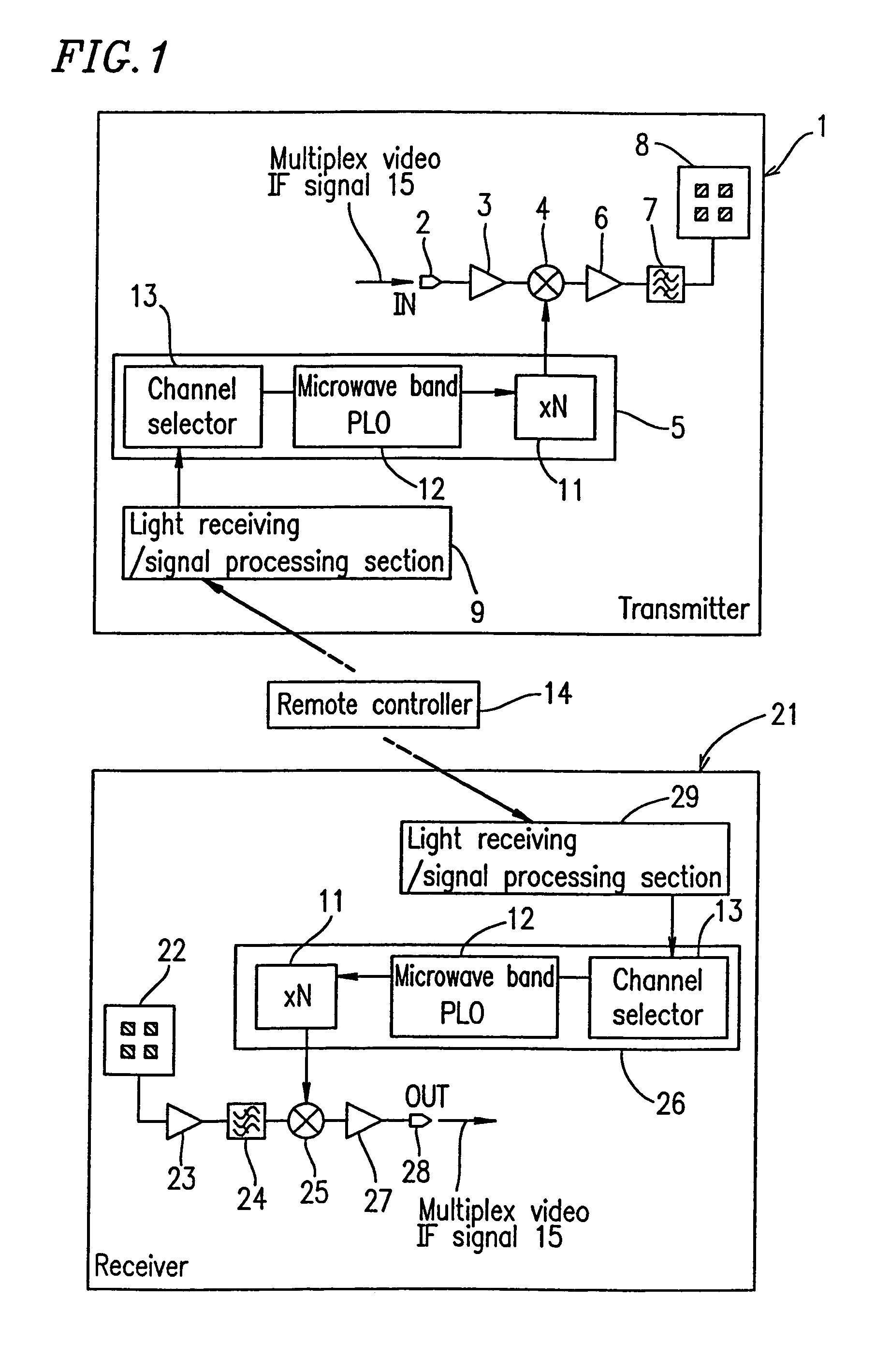
[0052]FIG. 1 is a block diagram showing radio-frequency radiocommunication apparatus according to embodiment 1 of the present invention. In embodiment 1, a milli-wave band video multiplex transmission which is performed inside a house is described.

[0053]The milli-wave band video multiplex transmission is generally used for transmitting data of the video media such as ground wave television broadcasting, satellite TV broadcasting, CATV, etc. In embodiment 1, a radio wave signal of the ground wave television broadcasting, an intermediate frequency signal of the satellite TV broadcast, and a transmission signal of the CATV are each directly up-converted to a milli-wave band signal at the transmitter side, and the transmitter outputs the milli-wave band signal as it is. On the other hand, a milli-wave band signal is received by a receiver and down-converted into a radio wave signal of the ground wave television broadcasting, a intermediate frequency signal of the satellite TV broadcasti...

embodiment 2

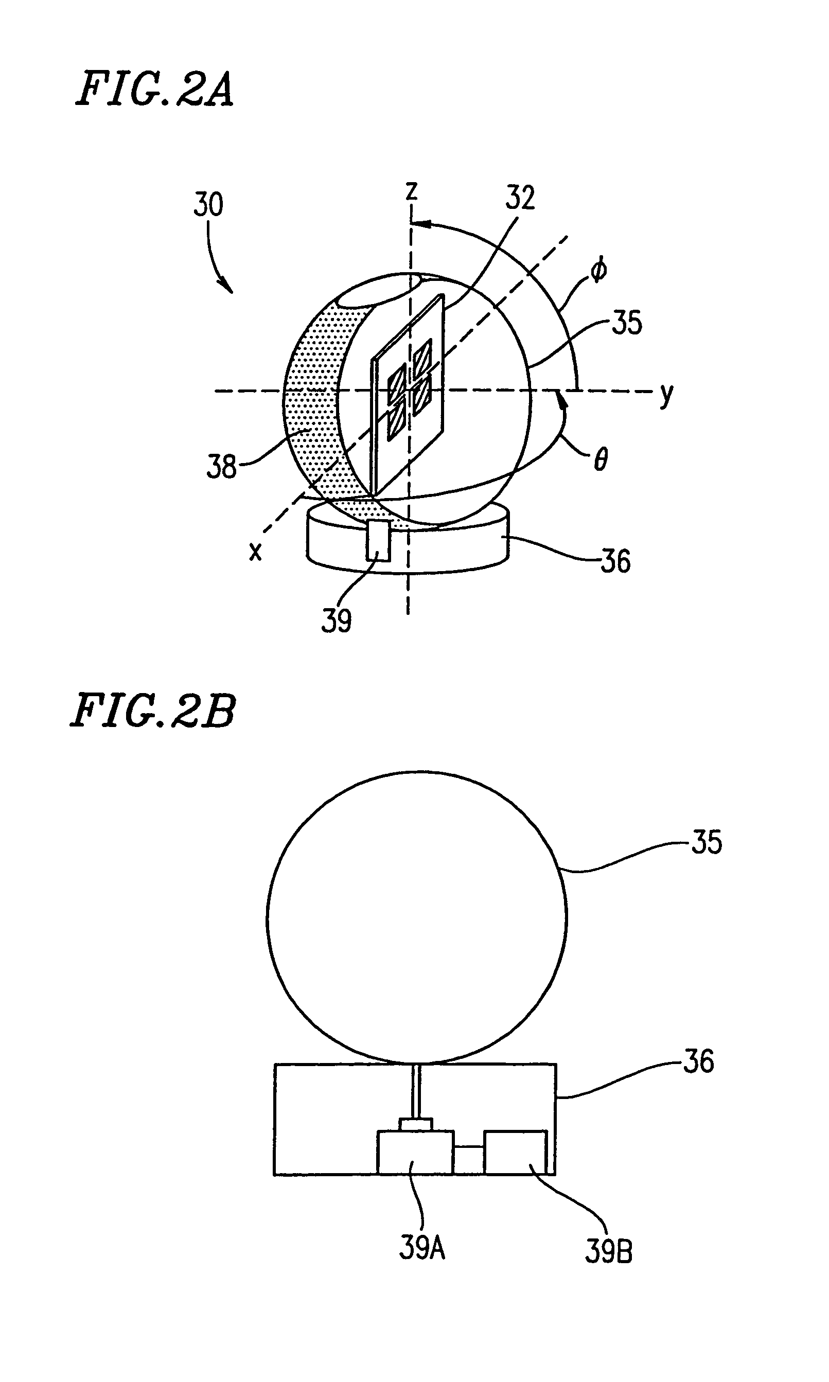
[0070]FIGS. 2A, 2B, 2C, and 2D show a radio-frequency radiocommunication apparatus according to embodiment 2 of the present invention. FIG. 2A is a perspective view showing a radio-frequency radiocommunication apparatus 30. FIG. 2B is a cross-sectional view of a turntable 36 of the radio-frequency radiocommunication apparatus 30. FIG. 2C is a cross-sectional view of a flat antenna 32 of the radio-frequency radiocommunication apparatus 30. FIG. 2D is a perspective view showing the flat antenna 32 of the radio-frequency radiocommunication apparatus 30. In embodiment 2, a milli-wave band video multiplex transmission which is performed inside a house is described.

[0071]As shown in FIG. 2C, antenna elements 32a are formed on a front face of the dielectric substrate 31, and a transmitting / receiving device 33 including a transmitting device 33A and a receiving device 33B is formed on a back face of the dielectric substrate 31 and is enclosed by a cover 34. Thus, the transmitting / receiving ...


PUM


Abstract

A radiocommunication apparatus includes a transmitting device and a receiving device. The transmitting device includes a first local oscillation section for selecting a frequency for a first local oscillation signal from a plurality of predetermined frequencies in order to output the first local oscillation signal, and a first frequency mixing section for mixing an input signal and the first local oscillation signal, thereby forming a transmission signal. The receiving device includes a second local oscillation section for selecting a frequency for a second local oscillation signal from the plurality of predetermined frequencies in order to output the second local oscillation signal, and a second frequency mixing section for mixing a received signal and the second local oscillation signal, thereby forming an output signal. The frequency for the first local oscillation signal and the frequency for the second local oscillation signal are selected such that the frequency for the first local oscillation signal and the frequency for the second local oscillation signal are identical to each other.

Description

BACKGROUND OF THE INVENTION[0001]1. Field of the Invention[0002]The present invention relates to a radio-frequency radiocommunication apparatus for transmitting / receiving radiocommunications in a range from a microwave band to a milli-wave band.[0003]2. Description of the Related Art[0004]A radiocommunication apparatus for transmitting / receiving radiocommunications in a range from a microwave band to a milli-wave band is structured, for example, as shown in FIG. 7. In FIG. 7, a transmitter 100 includes a baseband input terminal 101, a baseband amplifier 102, an FM modulator 103 using a voltage controlled oscillator, a frequency up-converter 104, and an antenna 105.[0005]On the other hand, a receiver 110 includes a baseband output terminal 111, an FM demodulator section 112, a frequency down-converter 113, a local oscillation section 114, and an antenna 115.[0006]In the transmitter 100, for example, a channel signal representing a image and a sound is input to the baseband input term...

Claims


Application Information

Patent Timeline
Patent Type & Authority Patents(United States)
IPC IPC(8): H04B1/40H04B1/26H01Q19/02H04B1/04
CPCH04B1/408
Inventor SUEMATSU, EIJI
Owner SHARP KK
Why Eureka
Try Eureka