Supercharge Your Innovation With Domain-Expert AI Agents!

Power management system for fuel injected engine

a technology of power management system and fuel injection engine, which is applied in the direction of electrical control, non-mechanical valves, instruments, etc., can solve the problems of power management, power supply of controllers, and insufficient power supply to meet the electrical demands of both the fuel injector and the variable intake valve closing mechanism

Active Publication Date: 2009-04-21
CATERPILLAR INC
View PDF12 Cites 4 Cited by
  • Summary
  • Abstract
  • Description
  • Claims
  • Application Information

AI Technical Summary

Benefits of technology

The present patent is about a power management system for combustion engines. It includes a fuel injector, a sensor, and a controller. The fuel injector injects multiple shots of fuel into the engine during a single injection event. The sensor senses the speed of the engine and sends a signal to the controller. The controller then limits the number of shots per injection event based on the speed signal. This system helps manage power supplied to the fuel injector and ensures efficient engine performance.

Problems solved by technology

If operating in a manner other than that predicted, resulting performance of the engine can be less than desired.
One problem associated with this type of arrangement may include power management.
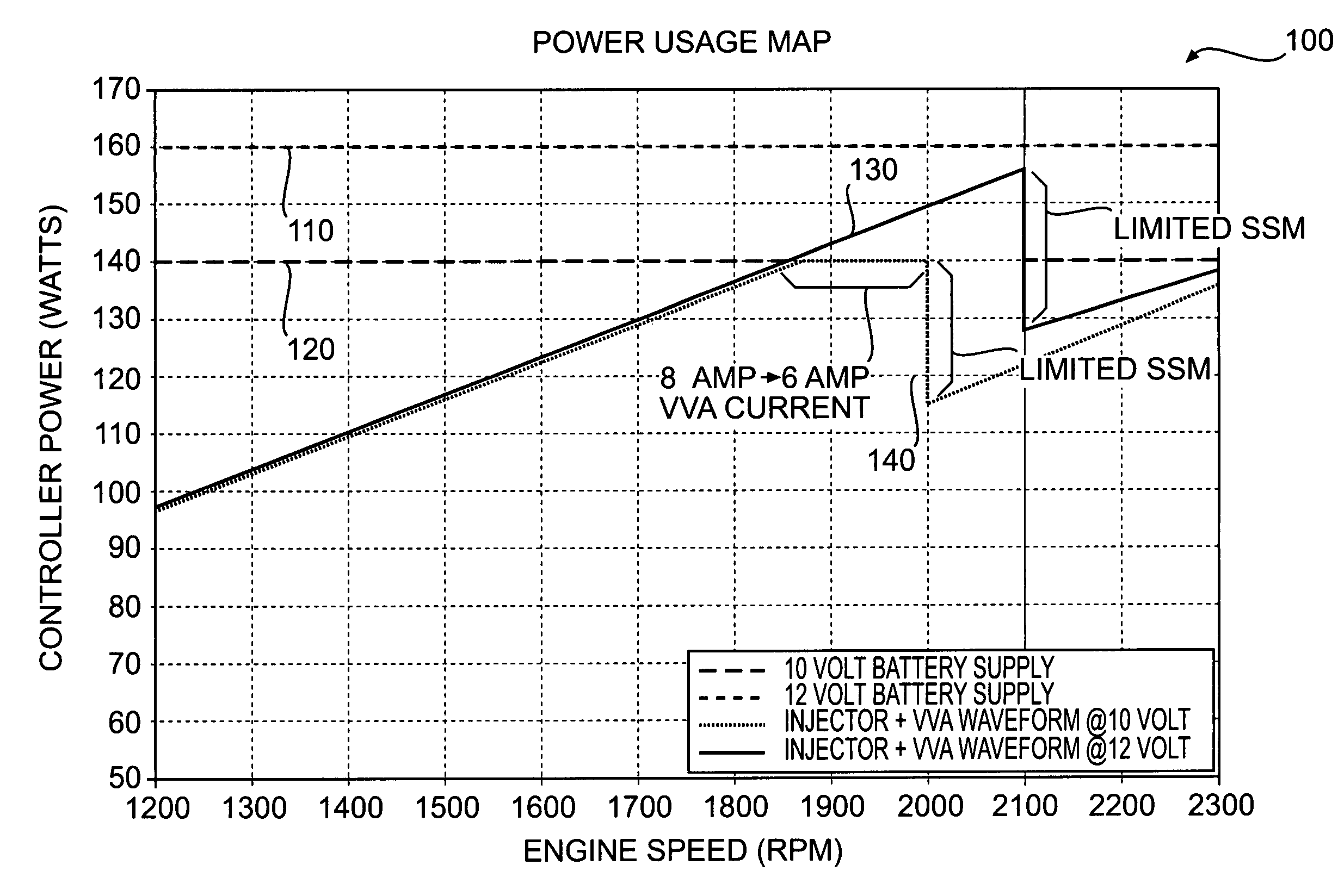
In particular, during certain operations of the internal combustion engine, such as at high engine speeds when multiple injections of fuel are required and when variable valve timing is simultaneously desired, the power supply of the controller may be insufficient to meet the electrical demands of both the fuel injector and the variable intake valve closing mechanism.
In these situations, because the supply of power is insufficient to meet the power demands, the operation of both the fuel injector and the variable intake valve closing mechanism may be negatively affected, resulting in poor and / or unpredictable performance of the engine.

Method used


Image

  • Power management system for fuel injected engine
  • Power management system for fuel injected engine
  • Power management system for fuel injected engine

Examples


Embodiment Construction

[0013]FIG. 1 illustrates an exemplary embodiment of a power source 10 having a control system 11. For the purposes of this disclosure, power source 10 is depicted and described as a four-stroke engine. One skilled in the art will recognize that power source 10 may embody any type of internal combustion engine such as, for example, a diesel engine, a gasoline engine, a gaseous fuel-powered engine, or any other suitable type of engine. Power source 10 may include an engine block 12 that defines a plurality of cylinders 14.

[0014]A piston 16 and a cylinder head 18 may be associated with each cylinder 14 to form a combustion chamber 20. Specifically, piston 16 may be slidably disposed within each cylinder 14 to reciprocate between a top-dead-center position and a bottom-dead-center position. Cylinder head 18 may be positioned to cap off an end of cylinder 14, thereby forming a combustion chamber 20. In the illustrated embodiment, power source 10 includes four combustion chambers 20. Howe...


PUM


Abstract

A power management system for a combustion engine is disclosed. The power management system has a fuel injector, a sensor, and a controller in communication with the sensor and the fuel injector. The fuel injector is operable to inject multiple shots of fuel into the combustion engine during a single injection event. The sensor is configured to sense a speed of the combustion engine and generate a signal indicative of the sensed speed. The controller is configured to limit the number of shots per injection event in response to the signal.

Description

TECHNICAL FIELD[0001]The present disclosure is directed to a power management system and, more particularly, to a power management system for use in a fuel injected engine.BACKGROUND[0002]An internal combustion engine typically includes at least one cylinder that receives a piston to form a combustion chamber. The piston is connected to a crankshaft such that a rotation of the crankshaft results in a corresponding reciprocating motion of the piston within the cylinder. Intake and exhaust valves associated with each combustion chamber are indirectly connected to the same crankshaft by way of a timing device such that a rotation of the crankshaft results in corresponding opening and closing movements of the intake and exhaust valves. Thus, the movements of engine valves and the motion of an associated piston, because of their connections to a common crankshaft, are synchronized.[0003]The timing of the opening and closing movements of the intake and exhaust valves relative to the recip...

Claims


Application Information

Patent Timeline
Patent Type & Authority Patents(United States)
IPC IPC(8): F02B3/00G06F17/00F01L9/20
CPCF01L9/04F02D41/402F02D2041/001F02D2400/14Y02T10/44Y02T10/40F01L9/20F02D41/40
Inventor BARNES, TRAVIS E.LEWIS, STEPHEN R.LOVE, W. JOHNMATZKE, TIMOTHY J.DEA, KEVIN L.
Owner CATERPILLAR INC
Features
  • R&D
  • Intellectual Property
  • Life Sciences
  • Materials
  • Tech Scout
  • Unparalleled Data Quality
  • Higher Quality Content
  • 60% Fewer Hallucinations
Learn More