Thermostatic valve for a fluid circuit, heat engine associated with a cooling circuit including such a valve, and method for manufacturing such a valve

Inactive Publication Date: 2009-04-21
VERNET SA
View PDF8 Cites 8 Cited by
  • Summary
  • Abstract
  • Description
  • Claims
  • Application Information

AI Technical Summary

Benefits of technology

[0008]The aim of the present invention is to propose a thermostatic valve with heating piston, the manufacture of

Problems solved by technology

The arrangement of such a “heating piston” within the valve, as proposed in EP-A-0 853 267, is however complex to produce and raises problems of providing a tight seal, in particular in the are

Method used


Image

  • Thermostatic valve for a fluid circuit, heat engine associated with a cooling circuit including such a valve, and method for manufacturing such a valve
  • Thermostatic valve for a fluid circuit, heat engine associated with a cooling circuit including such a valve, and method for manufacturing such a valve

Examples


Embodiment Construction

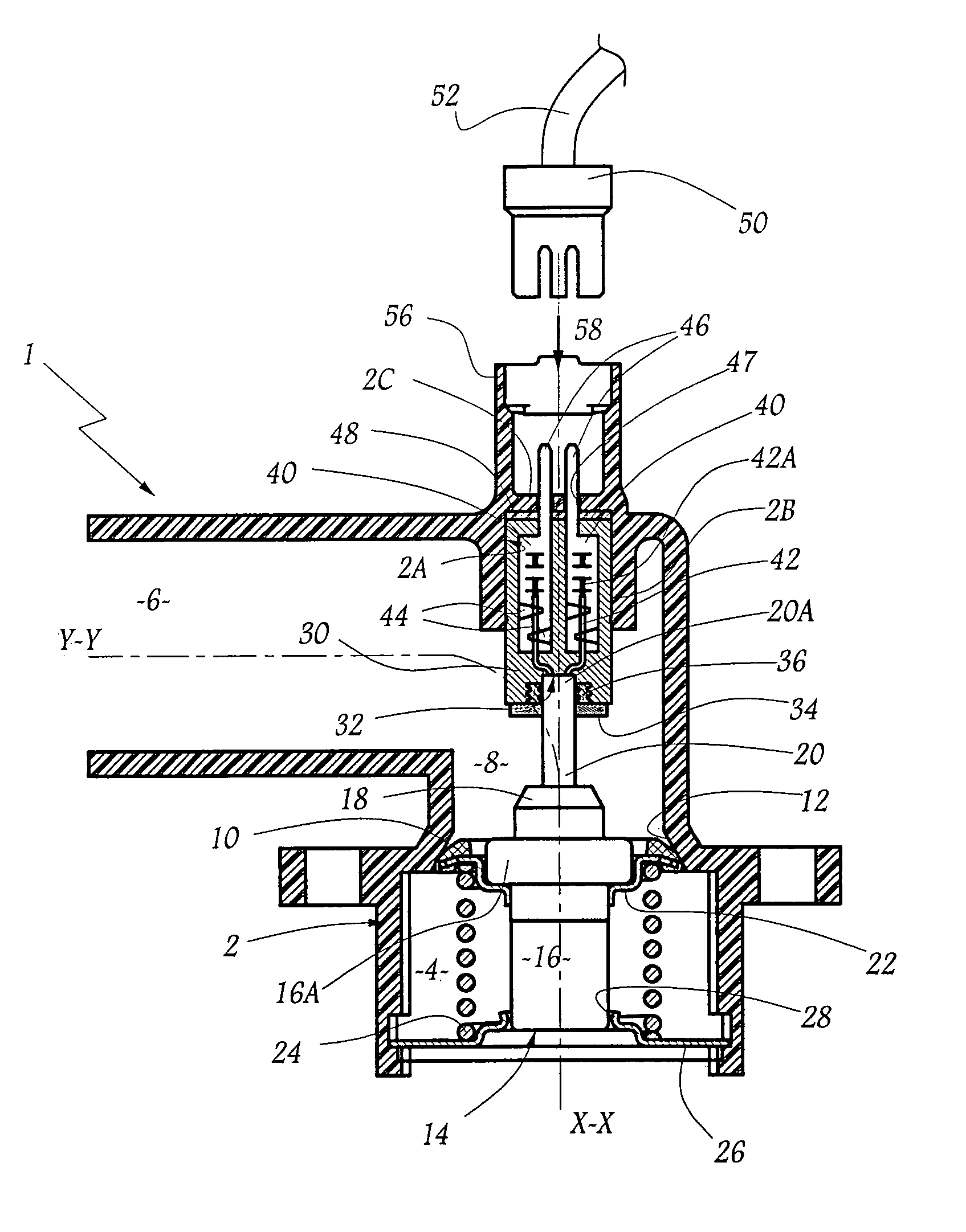
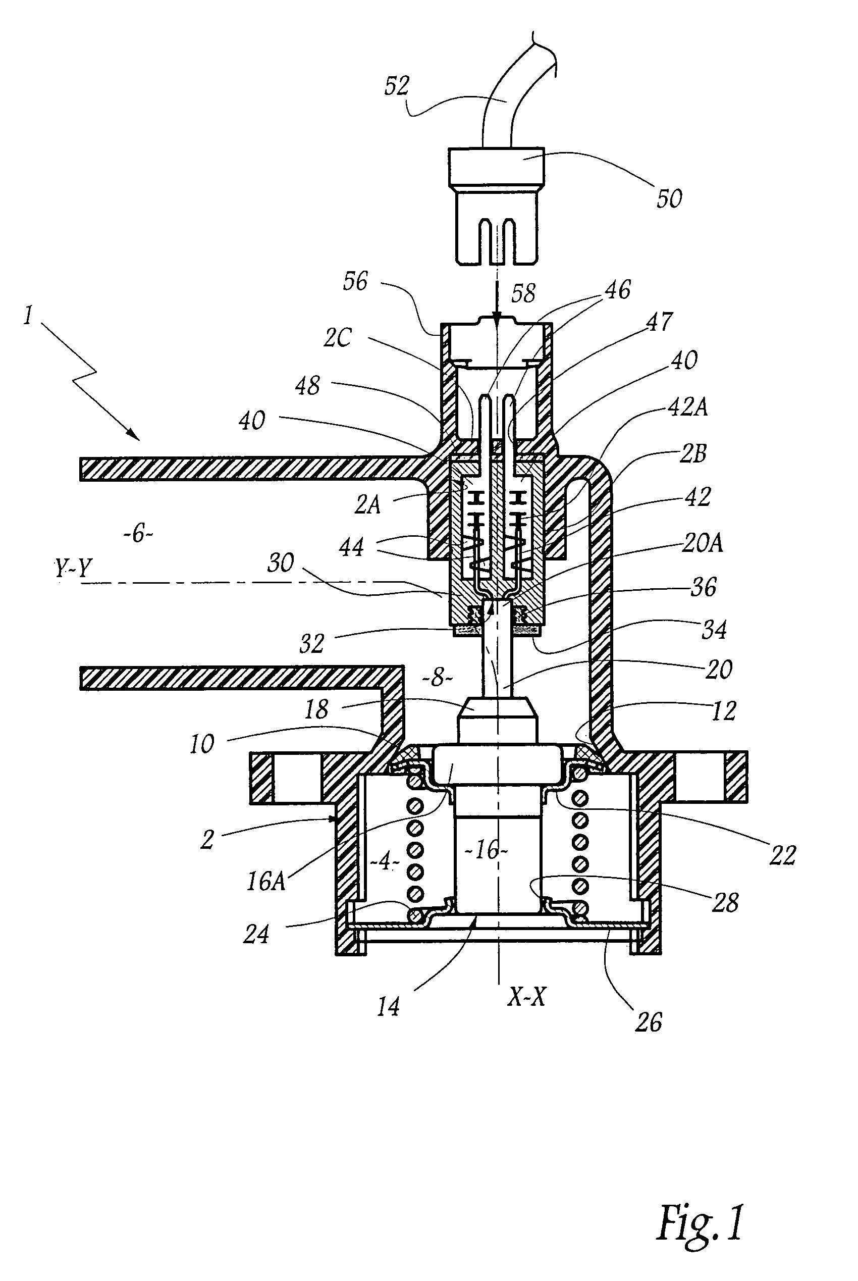
[0033]FIG. 1 shows a thermostatic valve 1 suitable for use with a cooling circuit, especially for a heat engine of a motor vehicle. The valve includes a rigid housing 2 made of a plastics material and including two conduits 4 and 6 which extend in respective longitudinal directions X-X and Y-Y substantially perpendicular to each other. The conduits open one into the other at an elbow junction zone 8 of the housing. By way of example, when the valve 1 is used in a cooling circuit of a heat engine, the conduit 4 is fed with cold fluid intended to communicate, under certain conditions detailed hereinafter, and via the zone 8, with the conduit 6 which forms an outlet of cold fluid in the direction of a heat exchanger.

[0034]The valve 1 is equipped with a regulating stop valve 10 for regulating the rate of flow of fluid from the conduit 4 to the conduit 6, via the zone 8. The stop valve 10 is associated with a seat 12 delimited internally by the housing 2. The stop valve is arranged to mo...


PUM


Abstract

A thermostatic valve mounted within a housing which defines a fluid circuit and wherein an internal valve seat is defined withing the housing, the thermostatic valve including a blocking valve component movable relative to the valve seat for opening and closing the fluid circuit, a thermostatic element for actuating the blocking valve and including a body and a piston that are relative movable with respect to one another and a base to which the piston is mounted, an electrical heating element mounted within the and piston of the thermostatic element for heating expansible material contained in the element, wherein one end of the piston is seated and sealed within a blind hole in the base and the base is seated and sealed within a blind cavity in the housing and which cavity has a bottom wall formed integrally with the housing through with electrical pins extend toward the outside of the housing.

Description

BACKGROUND OF THE INVENTION[0001]1. Field of the Invention[0002]The present invention concerns a thermostatic valve for a fluid circuit, including a thermostatic element of expansible material. It also concerns a heat engine associated with a cooling fluid circuit equipped with such a valve, and also a method for manufacturing such a valve.[0003]2. Brief Description of the Related Art[0004]In numerous applications of the field of fluidics, especially for the cooling of heat engines of vehicles, such valves are used for distributing a fluid entering by different circulation paths according to the temperature of the incoming fluid. In order to distribute the fluid according to other parameters, especially conditions outside the valve, such as ambient temperature or the load of the vehicle propelled by the engine equipped with the valve, it is known to provide means for electrical heating of the expansible material contained in the thermostatic element of the valve. It is then possible...

Claims


Application Information

Patent Timeline
IPC IPC(8): F23N1/00G05D23/02
CPCF01P7/167G05D23/2752G05D23/30F01P2070/04G05D23/1921G05D23/275
Inventor MARAUX, THIERRYBOULOY, ALAIN
Owner VERNET SA
Why Eureka
Try Eureka