Water treatment process for oilfield produced water

a technology for oilfield production and water treatment, applied in water/sewage treatment by ion exchange, dialysis systems, borehole/well accessories, etc., can solve the problems of increased injection pressure, difficult surface discharge of produced water, and difficult disposal of produced water

Active Publication Date: 2009-04-21
WATER & POWER TECH
View PDF139 Cites 92 Cited by
  • Summary
  • Abstract
  • Description
  • Claims
  • Application Information

AI Technical Summary

Benefits of technology

[0005]The present invention comprises a method and system for treating an aqueous liquid containing dissolved minerals and dissolved hydrocarbons. In an exemplary embodiment, the method comprises passing an aqueous liquid containing dissolved minerals and dissolved hydrocarbons through a warm lime softener at a pH of about 11, wherein the effluent from the warm lime softener may have the pH adjusted to about 9 with an acid to minimize the continued precipitation of insoluble compounds before passing the effluent through a microfiltration system prior to contacting a reverse osmosis system.

Problems solved by technology

Injecting steam into a well results in recovery of an oil / water mixture, where the water is typically removed from the oil and then contaminated produced water is lightly treated and recycled as poor quality steam back into the formation.
This eventually results in an increase of the injection pressures over time as the recycled water builds up in the formation and eventually blocks the movement and recovery of known oil reserves in the formation.
However, disposal of this produced water is problematic due to the presence of a large number of solutes, including minerals and organic compounds, which requires that the produced water be injected underground at a remote site or treated for surface discharge.
With increasing water quality standards, surface discharge of the produced water has become even more problematic and has produced a need for methods to treat the produced water prior to discharge.
Unfortunately, the solutes present in produced water vary depending upon its origin and the particular characteristics of the oil well site.
This has made the standardization of water treatment facilities difficult, if not impossible.

Method used


Image

  • Water treatment process for oilfield produced water
  • Water treatment process for oilfield produced water
  • Water treatment process for oilfield produced water

Examples


example i

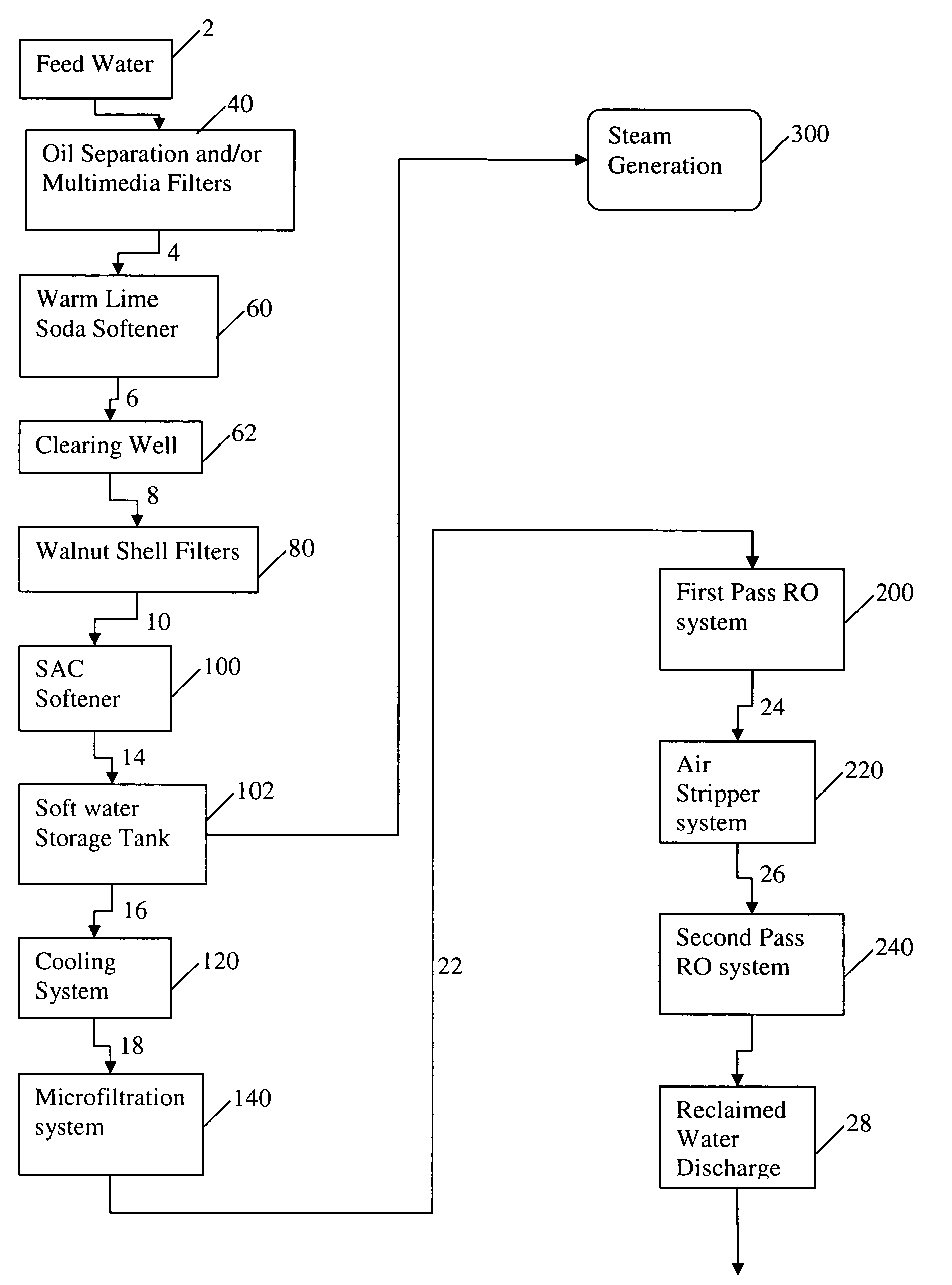
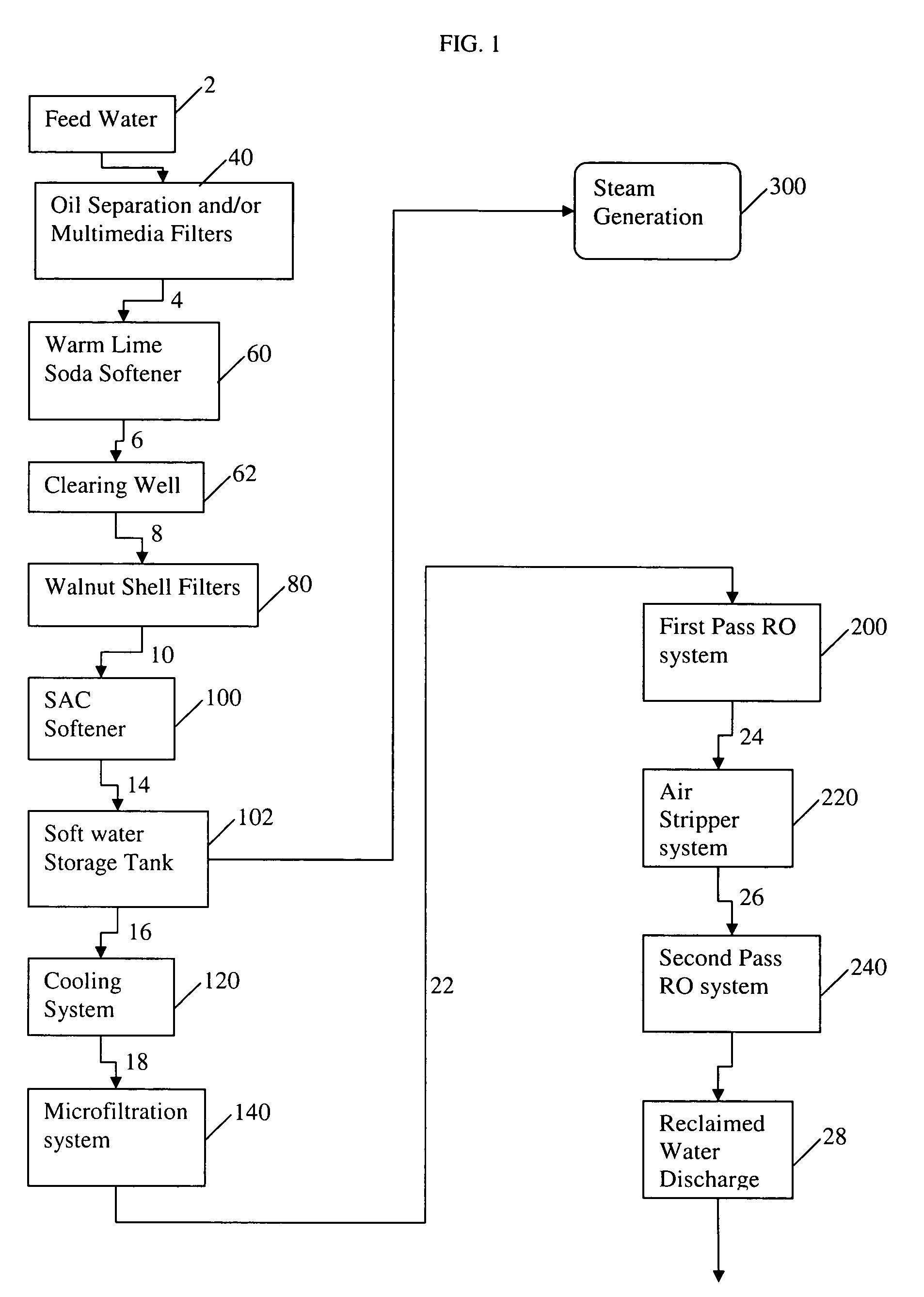
[0047]In an exemplary embodiment, a water treatment system as illustrated in FIG. 1 is designed. The designed flow rate of the warm lime softener system is about 2,095 gpm. The calculated Quicklime addition required is about 657.2 ppm as calcium oxide (CaO), where about 495.8 ppm is used for calcium, magnesium, and carbon dioxide removal as well as pH adjustment and about 161.4 ppm is added in excess. Since powdered Quicklime contains about 90% CAO this requires about 689.5 ppm of powdered Quicklime. The Quicklime will be slaked and diluted to a slurry between 5% and 12% by weight. The lime slurry will be circulated in a loop at a flow rate to maintain a desired pipe velocity and the required flow rate of slurry to provide the stated dosage will be metered from the described slurry flow loop.

[0048]The total calculated soda addition is about 275 ppm or about 397 gph (about 6.62 gpm), where the soda is added as a 10% wt solution. This system is designed to add soda at a maximal flow r...


PUM

PropertyMeasurementUnit
temperatureaaaaaaaaaa
pHaaaaaaaaaa

Abstract

The invention relates to a method and system for treating an aqueous liquid containing dissolved minerals and dissolved hydrocarbons. Method steps and apparatus for treating a waste water feed stream are disclosed which utilize a warm lime softening system in fluid communication with the waste water feed stream, wherein sludge from the warm lime softening system is recycled to improve lime utilization and enhance silica and boron removal without the addition of an external source of magnesium. In addition, a microfiltration system and / or an air stripper system may be used in fluid communication with at least one reverse osmosis system to produce a treatment water that meets state and federal guidelines for surface discharge.

Description

TECHNICAL FIELD[0001]The invention relates to the removal of solutes from an aqueous solvent, more particularly, to the removal of solutes present in oil field produced water to a level sufficient to meet state and / or federal requirements for discharge of the treated water.BACKGROUND[0002]As oil supplies diminish the need for improved recovery methods continually increases. One of the predominant methods used to improve viscous or heavy crude oil recovery involves injecting steam into the oil well, see U.S. Pat. No. 5,080,172. Injecting steam into a well results in recovery of an oil / water mixture, where the water is typically removed from the oil and then contaminated produced water is lightly treated and recycled as poor quality steam back into the formation. This eventually results in an increase of the injection pressures over time as the recycled water builds up in the formation and eventually blocks the movement and recovery of known oil reserves in the formation. As a result,...

Claims


Application Information

Patent Timeline
Patent Type & Authority Patents(United States)
IPC IPC(8): B01D61/00A61M1/16C02F1/44
CPCB01D61/58C02F9/00E21B43/34B01D61/022B01D61/025B01D61/147B01D2311/04B01D2311/06C02F1/20C02F1/40C02F1/42C02F1/441C02F1/444C02F1/66C02F5/025C02F2101/32B01D2311/12B01D2311/18B01D2311/2649B01D2311/2673B01D2311/106B01D2311/2623B01D61/026
Inventor LARAWAY, JAMES W.WEBER, RICHARD E.THOMAS, DONALD J.
Owner WATER & POWER TECH
Why Eureka
Try Eureka