Method for adjusting focus or tracking detection unit, and optical disc device
a tracking detection and optical disc technology, applied in the direction of digital signal error detection/correction, instruments, recording signal processing, etc., can solve the problems of coma aberration, considerable spherical aberration in the spot on the optical disc,
- Summary
- Abstract
- Description
- Claims
- Application Information
AI Technical Summary
Benefits of technology
Problems solved by technology
Method used
Image


Examples
embodiment 1
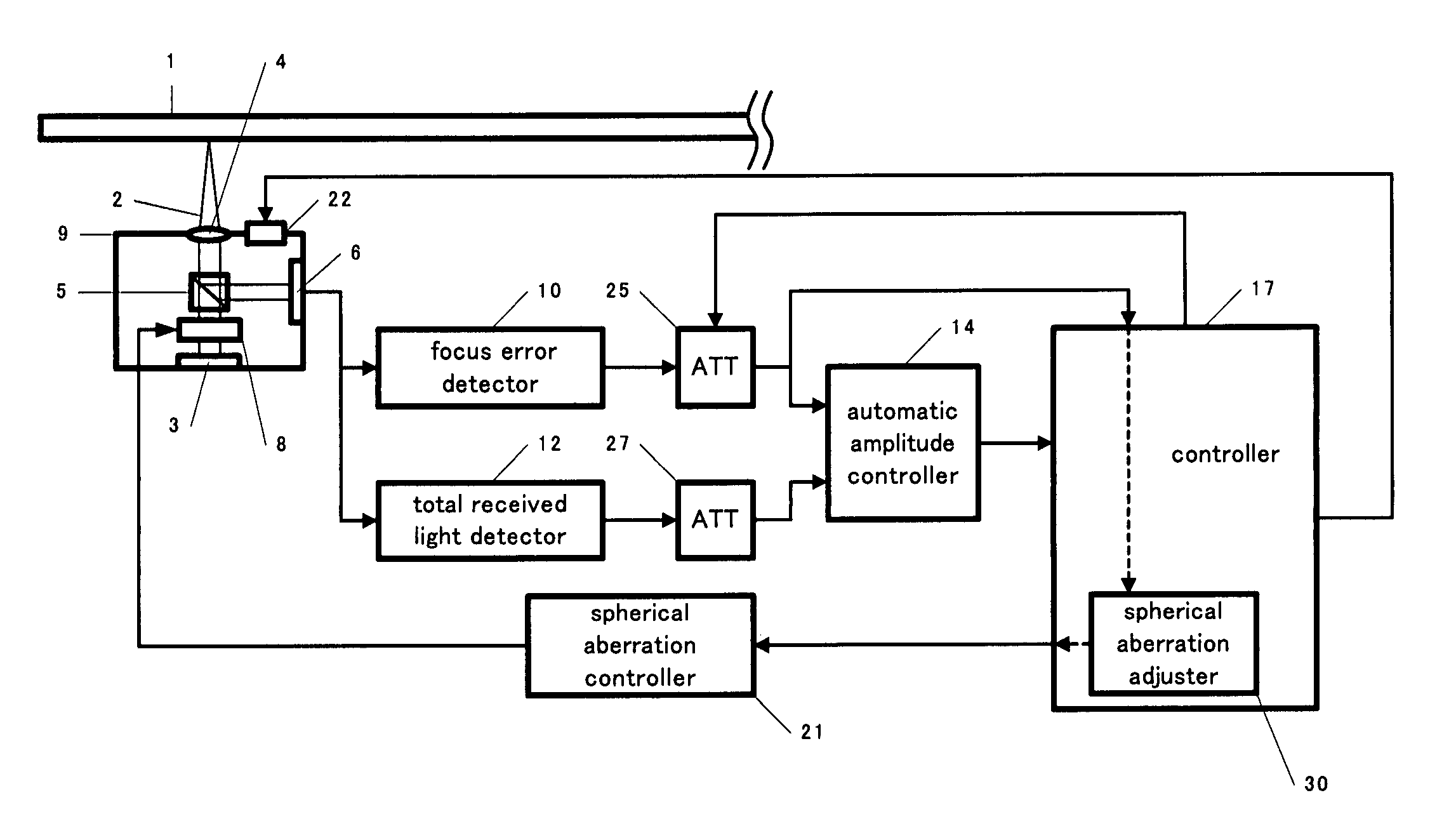
[0058]A first embodiment will be described through reference to FIGS. 1 and 20. FIG. 1 is a block diagram of the constitution of this embodiment, while FIG. 20 is a waveform diagram illustrating the waveforms of the total amount of received light and the FE signal amplitude when the amount of spherical aberration was roughly zero and when spherical aberration had occurred.
[0059]In FIG. 1, the optical irradiation unit 3 directs a light beam 2 at an optical disc 1 and irradiates the disc at a specific power. The irradiating light beam 2 passes through the beam splitter 5 and is focused by the focusing lens 4 on the information surface of the optical disc 1. The light beam 2 reflected by the optical disc 1 is directed by the beam splitter 5 to the light receiver 6. The light receiver 6 outputs the amount of received light as a signal. An optical head 9 is made up of the optical irradiation unit 3, the focusing lens 4, the beam splitter 5, the light receiver 6, and a spherical aberratio...
first modification of embodiment 1
[0065]The controller 17 shown in FIG. 4 has internally a spherical aberration adjuster 30. Signals from the ATT 25 are inputted to the spherical aberration adjuster 30. Also, the spherical aberration adjuster 30 is able to adjust the spherical aberration controller 21. The controller 17 raises and lowers the objective lens by driving the focus actuator 22. As a result, the amplitude (S-shaped) of a focus error is itself sent from the ATT 25 to the spherical aberration adjuster 30. The controller 17 drives the spherical aberration element 8 through the spherical aberration controller 21 so that the focus error amplitude will be substantially at its maximum, or so that the slope near the zero cross of a tracking error will be substantially at its maximum (step S4 in FIG. 5). After this, the controller 17 sets the ATT 25 so that the signal from the focus error detector 10 will be at a constant amplitude regardless of the reflectivity of the disc 1 (step S2 in FIG. 5).
[0066]As a result,...
second modification of embodiment 1
[0067]The spherical aberration rough adjustment in step S4 in the example of FIG. 1 may be performed using a signal from a tracking error detector (see FIG. 6). The controller 17 measures the tracking error signal after focusing control has been switched on, and drives the spherical aberration element 8 via the spherical aberration controller 21 so that the amplitude of this signal will substantially be at its maximum, or so that the slope of the tracking error near the zero cross will substantially be at its maximum. After this, the controller 17 sets the ATT 25 so that the signal from the spherical aberration controller 21 will have a constant amplitude, regardless of the reflectivity of the disc 1.
PUM
| Property | Measurement | Unit |
|---|---|---|
| thickness | aaaaa | aaaaa |
| thickness | aaaaa | aaaaa |
| reflectivity | aaaaa | aaaaa |
Abstract
Description
Claims
Application Information