Phosphor and manufacturing method of the same, and light emitting device using the phosphor

a technology of phosphor and manufacturing method, which is applied in the direction of discharge tube/lamp details, discharge tube luminescent composition, discharge tube luminescent screen, etc., can solve the problems of insufficient etc., to improve emission intensity and luminance, improve the effect of durability against heat and water

Inactive Publication Date: 2009-04-28
MITSUBISHI CHEM CORP
View PDF115 Cites 53 Cited by
  • Summary
  • Abstract
  • Description
  • Claims
  • Application Information

AI Technical Summary

Problems solved by technology

However, although such a phosphor containing nitrogen has an excellent durability against heat and water, has a flat excitation band in the wavelength range from the near ultraviolet / ultraviolet to blue color, and has an emission spectrum with a broad peak, the emission efficiency does not meet a satisfactory level when excited by the excitation light of the near ultraviolet / ultraviolet to blue color, and a sufficient emission intensity and luminance are not obtained.
Therefore, although the white LED illumination having an excellent durability can be manufactured, the emission intensity and luminance are insufficient.
Therefore, when the one chip type white LED illumination is manufactured by combining the near ultraviolet / ultraviolet LED and the blue LED or the like and the aforementioned phosphor containing nitrogen, the luminance which is a most important factor as the illumination becomes insufficient.

Method used


Image

  • Phosphor and manufacturing method of the same, and light emitting device using the phosphor
  • Phosphor and manufacturing method of the same, and light emitting device using the phosphor
  • Phosphor and manufacturing method of the same, and light emitting device using the phosphor

Examples


example 1

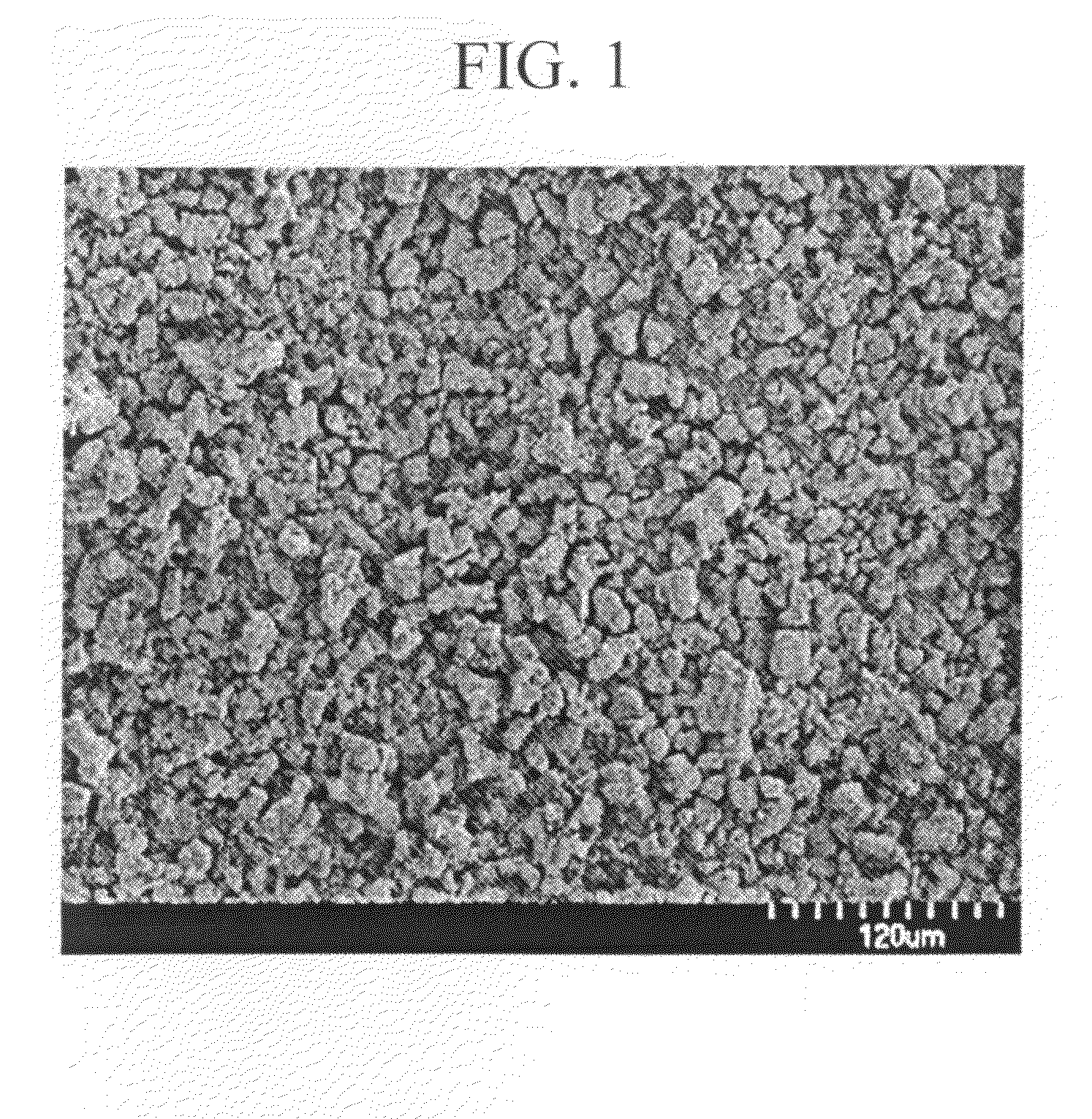
[0110]Commercially available SrCO3(3N), AlN(3N), Si3N4(3N), and CeO2(3N) were prepared, and among the raw materials, 0.970 mol of SrCO3, 1.0 mol of AlN, 4.5 / 3 mol of Si3N4, and 0.030 mol of CeO2 were weighed and mixed by using a mortar in an atmospheric air. The raw material thus mixed was put in a BN crucible, then temperature is increased to 1800° C. with an in-furnace pressure of 0.05 MPa set at 15° C. / min, retained and fired at 1800° C. for three hours, and then cooled from 1800° C. to 200° C. for one hour. Thereafter, the firing sample thus fired was crushed to a proper particle size by using the mortar in the atmospheric air, and the phosphor of the example 1 of the composition formula expressed by Sr2Al2Si9O2N14:Ce (where Ce / (Sr+Ce)=0.030) was obtained. Note that this composition formula is the composition calculated by a blending ratio of used raw materials. A result of a composition analysis of the powdery phosphor thus obtained is shown in table 1, and an SEM photograph o...

example 2

[0119]In the example 2, the phosphor of the example 2 is manufactured in the same way as the example 1, other than the molar ratio of each element of the example 1 is set to be Sr: Al : Si :Ce=0.970:1:5:0.030.

[0120]The commercially available SrCO3(3N), AlN(3N), Si3N4(3N), CeO2(3N) were prepared, and each raw material was measured in 0.970 mol of SrCO3, 1.0 mol of AlN, 5.0 / 3 mol of Si3N4, and 0.030 mol of CeO2, so that the molar ratio of each element was set to be Sr:Al:Si :Ce=0.970:1:5:0.030, and the raw materials thus measured was mixed in the atmosphere by using the mortar. The raw materials thus mixed was put in the crucible, and the temperature was increased to 1800° C. at 15° C. / min, with in-furnace pressure of 0.05 MPa, in a nitrogen atmosphere (flow state), and in this condition, the raw materials are retained and fired for 3 hours at 1800° C., then cooled from 1800° C. to 200° C. for 1 hour. Thereafter, a fired sample was pulverized in an atmospheric air to obtain a suitable...

example 3

[0127]In the example 3, the phosphor of the example 3 was manufactured in the same way as the example 1, other than replacing Ce with Eu, as the activator, in the phosphor expressed by the composition formula Sr2Al2Si9O2N14:Ce (where Ce / (Sr+Ce)=0.030) of the phosphor of the example 1. The molar ratio of each element was expressed by Sr:Al:Si:Eu=0.970:1:4.5:0.030, and each raw material was measured in 0.970 mol of SrCO3, 1.0 mol of AlN, 4.5 / 3 mol of Si3N4, and 0.030 / 2 mol of Eu2O3. The composition estimated by the raw material used and its blending ratio is expressed by Sr2Al2Si9O2N14:Eu (where Eu / (Sr 30 Eu)=0.030). In the same way as the example 1, the analysis result of the powdery phosphor thus obtained is shown in table 1.

[0128]

TABLE 1AVERAGESPECIFICSrSiPARTICLESURFACECOMPOSITIONz / (m +(wtAl(wtONCeEuOTHERSSIZEAREAFORMULAz)%)(wt %)%)(wt %)(wt %)(wt %)(wt %)(wt %)(μm)(m2 / g)EXAMPLE 1Sr2Al2Si9O2N14:Ce0.03024.87.0732.22.2530.51.231.9817.500.285EXAMPLE 2Sr3Al3Si15O3N23:Ce0.03023.76.1133...


PUM

PropertyMeasurementUnit
wavelengthaaaaaaaaaa
molar ratioaaaaaaaaaa

Abstract

To provide a phosphor having an emission spectrum with a broad peak in a range from green color to yellow color, having a broad and flat excitation band capable of using lights of broad range from near ultraviolet / ultraviolet to blue lights as excitation lights, and having excellent emission efficiency and luminance. The problem is solved by providing the phosphor expressed by a general composition formula MmAaBbOoNn:Z (where element M is one or more kinds of elements having bivalent valency, element A is one or more kinds of elements having tervalent valency, element B is one or more kinds of elements having tetravalent valency, O is oxygen, N is nitrogen, and element Z is one or more kinds of elements acting as the activator.), satisfying 4.0<(a+b) / m<7.0, a / m≧0.5, b / a >2.5, n>o, n=2 / 3 m+a+4 / 3 b−2 / 3 o.

Description

[0001]This nonprovisional application claims the benefit of U.S. Provisional Application Ser. No. 60 / 658,198, filed Mar. 4, 2005.TECHNICAL FIELD OF THE INVENTION[0002]The present invention relates to a phosphor used for a cathode-ray tube (CRT), a display such as a field emission display (FED) and a plasma display (PDP), and an illumination device such as a fluorescent lamp and a fluorescent display tube, and a phosphor containing nitrogen used for an illumination device such as a crystal liquid back light and a method of manufacturing therefore, and also to a light emitting device such as a white LED illumination in which a semiconductor light emitting element (LED) and the phosphor are combined.BACKGROUND OF THE INVENTION[0003]At present, a discharge type fluorescent lamp and an incandescent bulb used as the illumination device involve problems that a harmful substance such as mercury is contained, and life span is short. However, in recent years, a high luminescence LED emitting ...

Claims


Application Information

Patent Timeline
Patent Type & Authority Patents(United States)
IPC IPC(8): C09K11/08C09K11/55C09K11/59C09K11/64
CPCC09K11/0883C09K11/7721C09K11/7734H05B33/14H01L33/502C09K11/77218C09K11/77348
Inventor SAKANE, KENJINAGATOMI, AKIRA
Owner MITSUBISHI CHEM CORP
Why Eureka
Try Eureka