Drive circuit for an injector arrangement

a drive circuit and injector technology, applied in the direction of electrical control, device details, electrical control, etc., can solve the problems of complex known conventional drive circuitry for controlling piezoelectric fuel injectors, requiring extensive energy, and requiring relatively high currents (tens of amps) in order to function properly, etc., to achieve the effect of small and cheaper voltage supply means, reduced size and cost of voltage supply means, and cheaper and more controllable drive circuits

Inactive Publication Date: 2009-04-28
DELPHI INT OPERATIONS LUXEMBOURG S A R L
View PDF14 Cites 13 Cited by
  • Summary
  • Abstract
  • Description
  • Claims
  • Application Information

AI Technical Summary

Benefits of technology

[0011]In a first embodiment of the present invention, the regeneration switch means is preferably operable at the end of the charging phase to transfer charge from the voltage supply means to the first charge storage means, and then to the second charge storage means from the first charge storage means via the energy storage device. Most preferably, the regeneration switch means is used to transfer charge from the voltage supply means to both the first and second voltage rails such that the voltage across the first and second charge storage means is increased. In this embodiment, the voltage supply means advantageously comprises a vehicle battery and a transformer to step-up the voltage generated by the vehicle battery to a higher voltage suitable for applying to the first charge storage means. An advantage of this embodiment of the present invention is that the voltage supply means is only used to increase the charge on the first charge storage means, and therefore a smaller and cheaper voltage supply means may be used than in known drive circuits. A further advantage of this embodiment of the present invention is that if the voltage supply means provides a 42 Volt charging system, and the injectors are operable at a similar voltage, then a transformer may not be required, thereby leading to a further reduction in the size and cost of the voltage supply means.
[0012]In a second embodiment of the present invention, the regeneration switch means is preferably operable at the end of the charging phase to transfer charge from the voltage supply means to the first charge storage means and also to the second charge storage means prior to the subsequent discharging phase. Most preferably, the regeneration switch means is used to transfer charge from the voltage supply means to the second voltage rail such that the voltage across the second charge storage means is increased (the first voltage rail being supplied by the voltage supply means). Preferably the voltage supply means comprises a vehicle battery, and advantageously no transformer is required to step up the voltage generated by the vehicle battery. The advantage of this embodiment is that there is no need to provide a dedicated power supply (such as a transformer) which leads to a cheaper and more controllable drive circuit than those known in the prior art.
[0027]The efficiency of the fuel injectors determines how much energy is removed from the first and second charge storage means, and also determines a peak current in the energy storage device over a period of time to regenerate the charge stored on the first and second charge storage means. In other words, the more efficient the injector, the less current in the energy storage device, and the shorter regeneration time required. It is therefore a preferable feature of the present invention that the regeneration time is controllable.

Problems solved by technology

However, piezoelectric fuel injectors also generally require relatively high voltages (typically in the hundreds of volts) and high currents (tens of amps) in order to function properly.
Known conventional drive circuitry for controlling a piezoelectric fuel injector is generally complicated and requires extensive energy.
However, a disadvantage of providing a dedicated power supply of this size is increased cost.
Thus, a further disadvantage is that the controller required to control the drive circuit must be of large size.
The drive circuit comprises a single voltage supply rail and operates in a purely unidirectional manner (i.e., it does not provide negative voltages), and therefore cannot be used to drive bi-directional fuel injectors which require both negative and positive voltages.
Another problem with current drive circuits is that it is difficult to control dynamically the voltage across the large reservoir capacitors should the higher 42 voltage supply (or a lower voltage supply) be required.

Method used


Image

  • Drive circuit for an injector arrangement
  • Drive circuit for an injector arrangement
  • Drive circuit for an injector arrangement

Examples


first embodiment

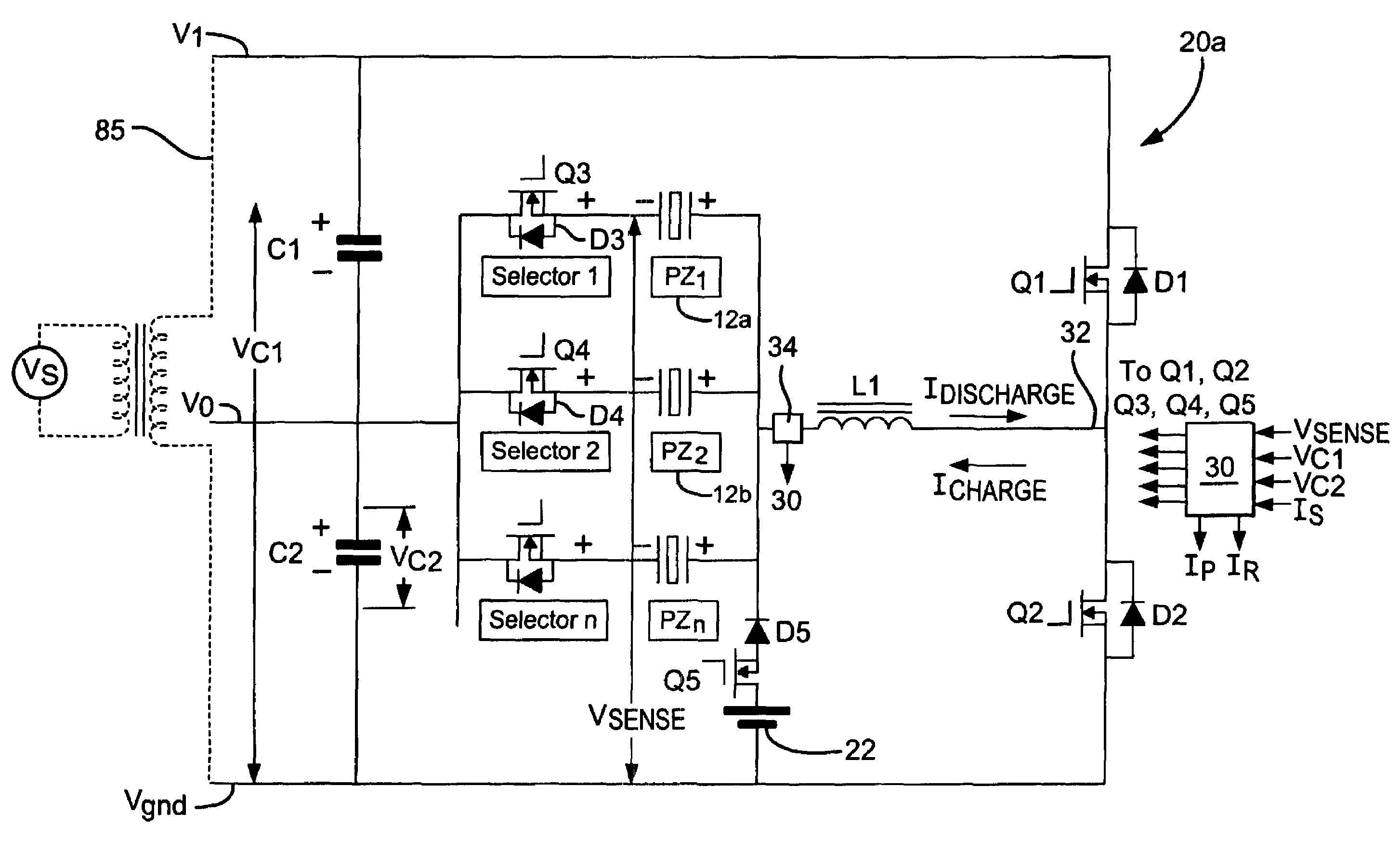
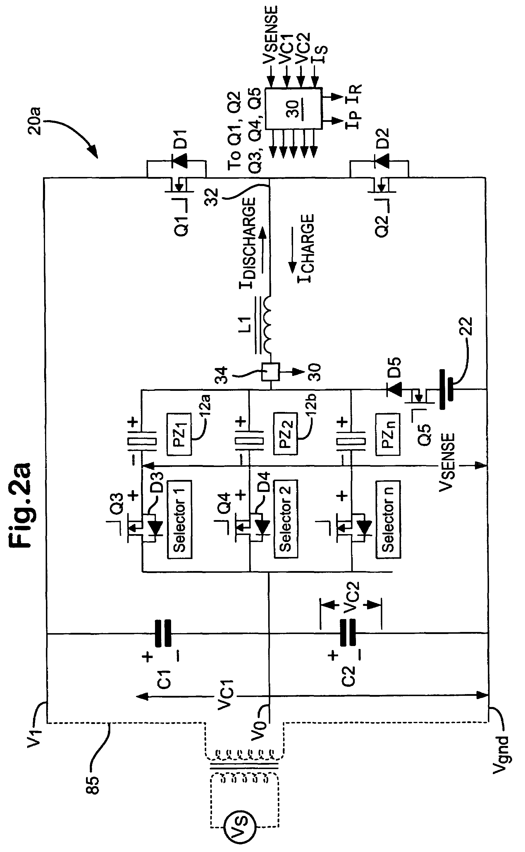
[0050]The piezoelectric drive circuit 20a, according to the present invention, is illustrated in detail in the block / circuit diagram of FIG. 2a. The drive circuit 20a includes first and second voltage supply rails V0 and V1, and is generally configured as a half H-bridge having a middle circuit current path 32 which serves as a bi-directional current path. The middle circuit branch 32 includes an inductor L1 and a current sensing and control means 34, which is coupled in series with a parallel connection of the injectors 12a and 12b and associated switching circuitry. Each injector 12a and 12b has the electrical characteristics of a capacitor, with its piezoelectric actuator stack being chargeable to hold a voltage which is the potential difference between the charge (+) and discharge (−) terminals of the injector 12a and 12b. Charging and discharging of each injector 12a,12b is achieved by controlling the flow of current through the bi-directional current path 32 by means of the mi...

second embodiment

[0087]Referring again to FIG. 4, with the regeneration switch Q5 activated, while the discharge switch Q2 is on, current is drawn from the vehicle battery 22 (or the PSU 36) and passes through the regeneration switch Q5, the diode D6, the inductor L1, the discharge switch Q2, and through the second energy storage capacitor C2 (as illustrated by the dashed arrows) such that the energy on the second capacitor C2 decreases. When the discharge switch Q2 is switched off, current flows from the first capacitor C1, through the regeneration switch Q5, the diode D6, the inductor L1, and the diode D1 associated with the charge switch Q1, such that the energy on the first capacitor C1 increases (shown by the bold arrows). Thus, during the regeneration phase in the invention, the inductor L1 transfers energy from the second energy storage capacitor C2 to the first energy storage capacitor C1, and the vehicle battery 22 (or the PSU 36) maintains the voltage on C2. Thus, the regeneration phase is...


PUM


Abstract

A drive circuit (20a,20b) for an injector arrangement having at least one piezoelectric injector (12a,12b) is described. The drive circuit comprises: a first charge storage means (C2) for operative connection with the injector (12a,12b) during a discharging phase so as to discharge current to flow therethrough, thereby to initiate an injection event; a second charge storage means (C1) for operative connection with the injector (12a,12b) during a charging phase so as to cause a charging current to flow therethrough, thereby to terminate the injection event; a switch means (Q1,Q2) for controlling whether the first charge storage means (C2) is operably connected to the injector or whether the second charge storage means (C1) is operably connected to the injector; a first voltage supply rail at a first voltage level; a second voltage supply rail at a second voltage level higher than the first; a voltage supply means (22,36); and regeneration switch means (Q5,Q2, L1) operable at the end of the charging phase to transfer charge from the voltage supply means to at least the second charge storage means (C1) via an energy storage device (L1) prior to a subsequent discharging phase.

Description

TECHNICAL FIELD[0001]The present invention relates to a drive circuit for an injector arrangement. It relates particularly, although not exclusively, to a drive circuit for an injector arrangement for an internal combustion engine, the injector arrangement including at least one injector of the type having a piezoelectric actuator for controlling injector valve needle movement.BACKGROUND ART[0002]Automotive vehicle engines are generally equipped with fuel injectors for injecting fuel (e.g., gasoline or diesel fuel) into the individual cylinders or intake manifold of the engine. The engine fuel injectors are coupled to a fuel rail which contains high pressure fuel that is delivered by way of a fuel delivery system. In diesel engines, conventional fuel injectors typically employ a valve that is actuated to open and close to control the amount of fluid fuel metered from the fuel rail and injected into the corresponding engine cylinder or intake manifold.[0003]One type of fuel injector ...

Claims


Application Information

Patent Timeline
Patent Type & Authority Patents(United States)
IPC IPC(8): H01L41/09F02D41/20H01L41/04
CPCF02D41/2096H02N2/067F02D2041/2006F02D2041/2051F02D2041/2058F02D2041/2072
Inventor MARTIN, STEVEN J
Owner DELPHI INT OPERATIONS LUXEMBOURG S A R L
Why Eureka
Try Eureka